
User's Manual
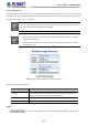
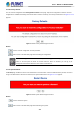
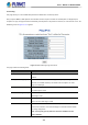
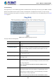
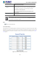
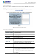
Table Of Contents
- 1. INTRODUCTION
- 2. INSTALLATION
- 3. SWITCH MANAGEMENT
- 4. WEB CONFIGURATION
- 4.1 Main Web page
- 4.2 System
- 4.2.1 Management
- 4.2.1.1 System Information
- 4.2.1.2 IP Configuration
- 4.2.1.3 IP Status
- 4.2.1.4 ARP Table
- 4.2.1.5 Users Configuration
- 4.2.1.6 Privilege Levels
- 4.2.1.7 NTP Configuration
- 4.2.1.7.1 System Time Correction Manually
- 4.2.1.8 Time Configuration
- 4.2.1.9 UPnP
- 4.2.1.10 DHCP Relay
- 4.2.1.11 DHCP Relay Statistics
- 4.2.1.12 CPU Load
- 4.2.1.13 System Log
- 4.2.1.14 Detailed Log
- 4.2.1.15 Remote Syslog
- 4.2.1.16 SMTP Configuration
- 4.2.1.17 Fault Alarm
- 4.2.1.18 Digital Input/Output
- 4.2.2 Simple Network Management Protocol
- 4.2.3 RMON
- 4.2.4 DHCP server
- 4.2.5 Remote Management
- 4.2.1 Management
- 4.3 Switching
- 4.3.1 Port Management
- 4.3.2 Link Aggregation
- 4.3.3 VLAN
- 4.3.3.1 VLAN Overview
- 4.3.3.2 IEEE 802.1Q VLAN
- 4.3.3.3 VLAN Port Configuration
- 4.3.3.4 VLAN Membership Status
- 4.3.3.5 VLAN Port Status
- 4.3.3.6 Private VLAN
- 4.3.3.7 Port Isolation
- 4.3.3.8 VLAN setting example:
- 4.3.3.9 MAC-based VLAN
- 4.3.3.10 IP Subnet-based VLAN Membership Configuration
- 4.3.3.11 Protocol-based VLAN
- 4.3.3.12 Protocol-based VLAN Membership
- 4.3.2.13 VLAN Translation
- 4.3.4 Spanning Tree Protocol
- 4.3.5 Multicast
- 4.3.6 MLD Snooping
- 4.3.7 MVR (Multicast VLAN Registration)
- 4.3.8 LLDP
- 4.3.9 MAC Address Table
- 4.3.10 Loop Protection
- 4.3.11 UDLD
- 4.3.12 GVRP
- 4.3.13 PTP
- 4.3.14 Link OAM
- 4.4 Quality of Service
- 4.4.2 Bandwidth Control
- 4.4.4.2 DSCP-based QoS
- 4.5 Security
- 4.6 Ring
- 4.7 Maintenance
- 5. COMMAND LINE MODE
- 6. SWITCH OPERATION
- 7. TROUBLESHOOTING
- APPENDIX A: Networking Connection
- APPENDIX B : GLOSSARY

User’s Manual of MGSD-10080F
386
4.7.2.2 IPv6 Ping
This page allows you to issue ICMPv6 ping packets to troubleshoot IPv6 connectivity issues. After you press “Start”, 5 ICMPv6
packets are transmitted, and the sequence number and roundtrip time are displayed upon reception of a reply. The page
refreshes automatically until responses to all packets are received, or until a timeout occurs. The ICMPv6 ping screen in Figure
4-7-2-2 appears.
Figure 4-7-2-2: ICMPv6 Ping Page Screenshot
The page includes the following fields:
Object Description
• Hostname or IP Address
The address of the destination host, either as a symbolic hostname or an IP
Address.
• Payload Size (bytes)
Determines the size of the ICMP data payload in bytes (excluding the size of
Ethernet, IP and ICMP headers). The default value is 56 bytes. The valid
range is 2-1452 bytes.
• Payload Data Pattern
Determines the pattern used in the ICMP data payload. The default value is 0.
The valid range is 0-255.
• Packet Count (packets)
Determines the number of PING requests sent. The default value is 5. The
valid range is 1-60.
• VID for Source Interface
This field can be used to force the test to use a specific local VLAN interface
as the source interface. Leave this field empty for automatic selection based
on routing configuration.
Note: You may only specify either the VID or the IP Address for the
source interface.
• Source Port Number
This field can be used to force the test to use a specific local interface with the
specified port number as the source interface. The specified port must be
configured with a suitable IP address. Leave this field empty for automatic
selection based on routing configuration.
Note: You may only specify either the Source Port Number or the IP