
User's Manual
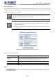
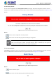
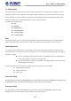
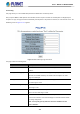
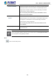
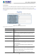
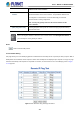
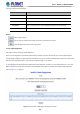
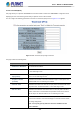
Table Of Contents
- 1. INTRODUCTION
- 2. INSTALLATION
- 3. SWITCH MANAGEMENT
- 4. WEB CONFIGURATION
- 4.1 Main Web page
- 4.2 System
- 4.2.1 Management
- 4.2.1.1 System Information
- 4.2.1.2 IP Configuration
- 4.2.1.3 IP Status
- 4.2.1.4 ARP Table
- 4.2.1.5 Users Configuration
- 4.2.1.6 Privilege Levels
- 4.2.1.7 NTP Configuration
- 4.2.1.7.1 System Time Correction Manually
- 4.2.1.8 Time Configuration
- 4.2.1.9 UPnP
- 4.2.1.10 DHCP Relay
- 4.2.1.11 DHCP Relay Statistics
- 4.2.1.12 CPU Load
- 4.2.1.13 System Log
- 4.2.1.14 Detailed Log
- 4.2.1.15 Remote Syslog
- 4.2.1.16 SMTP Configuration
- 4.2.1.17 Fault Alarm
- 4.2.1.18 Digital Input/Output
- 4.2.2 Simple Network Management Protocol
- 4.2.3 RMON
- 4.2.4 DHCP server
- 4.2.5 Remote Management
- 4.2.1 Management
- 4.3 Switching
- 4.3.1 Port Management
- 4.3.2 Link Aggregation
- 4.3.3 VLAN
- 4.3.3.1 VLAN Overview
- 4.3.3.2 IEEE 802.1Q VLAN
- 4.3.3.3 VLAN Port Configuration
- 4.3.3.4 VLAN Membership Status
- 4.3.3.5 VLAN Port Status
- 4.3.3.6 Private VLAN
- 4.3.3.7 Port Isolation
- 4.3.3.8 VLAN setting example:
- 4.3.3.9 MAC-based VLAN
- 4.3.3.10 IP Subnet-based VLAN Membership Configuration
- 4.3.3.11 Protocol-based VLAN
- 4.3.3.12 Protocol-based VLAN Membership
- 4.3.2.13 VLAN Translation
- 4.3.4 Spanning Tree Protocol
- 4.3.5 Multicast
- 4.3.6 MLD Snooping
- 4.3.7 MVR (Multicast VLAN Registration)
- 4.3.8 LLDP
- 4.3.9 MAC Address Table
- 4.3.10 Loop Protection
- 4.3.11 UDLD
- 4.3.12 GVRP
- 4.3.13 PTP
- 4.3.14 Link OAM
- 4.4 Quality of Service
- 4.4.2 Bandwidth Control
- 4.4.4.2 DSCP-based QoS
- 4.5 Security
- 4.6 Ring
- 4.7 Maintenance
- 5. COMMAND LINE MODE
- 6. SWITCH OPERATION
- 7. TROUBLESHOOTING
- APPENDIX A: Networking Connection
- APPENDIX B : GLOSSARY

User’s Manual of MGSD-10080F
383
4.7.2 Diagnostics
This section provides the Physical layer and IP layer network diagnostics tools for troubleshooting. The diagnostic tools are
designed for network manager to help them quickly diagnose problems between point to point and better service customers.
Use the Diagnostics menu items to display and configure basic administrative details of the Managed Metro Switch. Under
System the following topics are provided to configure and view the system information:
This section has the following items:
Ping
IPv6 Ping
Remote IP Ping
Cable Diagnostics
Tracerouter (IPv4)
Tracerouter (IPv6)
Ping
The ping and IPv6 ping allow you to issue ICMP PING packets to troubleshoot IP connectivity issues. The Managed Metro
Switch transmit ICMP packets, and the sequence number and roundtrip time are displayed upon reception of a reply.
Cable Diagnostics
The Cable Diagnostics performing tests on copper cables. These functions have the ability to identify the cable length and
operating conditions, and to isolate a variety of common faults that can occur on the Cat5 twisted-pair cabling. There might be
two statuses as follow:
If the link is established on the twisted-pair interface in 1000BASE-T mode, the Cable Diagnostics
can run without disruption of the link or of any data transfer.
If the link is established in 100BASE-TX or 10BASE-T, the Cable Diagnostics cause the link to drop
while the diagnostics are running.
After the diagnostics are finished, the link is reestablished. And the following functions are available.
Coupling between cable pairs.
Cable pair termination
Cable Length
Traceroute (IPv4)
This page allows you to perform a traceroute test over IPv4 towards a remote host. traceroute is a diagnostic tool
for displaying the route and measuring transit delays of packets across an IPv4 network.
Traceroute (IPv6)
This page allows you to perform a traceroute test over IPv6 towards a remote host. traceroute is a diagnostic tool for
displaying the route and measuring transit delays of packets across an IPv6 network.