
User's Manual
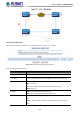
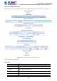
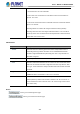
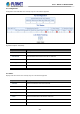
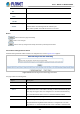
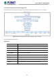
Table Of Contents
- 1. INTRODUCTION
- 2. INSTALLATION
- 3. SWITCH MANAGEMENT
- 4. WEB CONFIGURATION
- 4.1 Main Web page
- 4.2 System
- 4.2.1 Management
- 4.2.1.1 System Information
- 4.2.1.2 IP Configuration
- 4.2.1.3 IP Status
- 4.2.1.4 ARP Table
- 4.2.1.5 Users Configuration
- 4.2.1.6 Privilege Levels
- 4.2.1.7 NTP Configuration
- 4.2.1.7.1 System Time Correction Manually
- 4.2.1.8 Time Configuration
- 4.2.1.9 UPnP
- 4.2.1.10 DHCP Relay
- 4.2.1.11 DHCP Relay Statistics
- 4.2.1.12 CPU Load
- 4.2.1.13 System Log
- 4.2.1.14 Detailed Log
- 4.2.1.15 Remote Syslog
- 4.2.1.16 SMTP Configuration
- 4.2.1.17 Fault Alarm
- 4.2.1.18 Digital Input/Output
- 4.2.2 Simple Network Management Protocol
- 4.2.3 RMON
- 4.2.4 DHCP server
- 4.2.5 Remote Management
- 4.2.1 Management
- 4.3 Switching
- 4.3.1 Port Management
- 4.3.2 Link Aggregation
- 4.3.3 VLAN
- 4.3.3.1 VLAN Overview
- 4.3.3.2 IEEE 802.1Q VLAN
- 4.3.3.3 VLAN Port Configuration
- 4.3.3.4 VLAN Membership Status
- 4.3.3.5 VLAN Port Status
- 4.3.3.6 Private VLAN
- 4.3.3.7 Port Isolation
- 4.3.3.8 VLAN setting example:
- 4.3.3.9 MAC-based VLAN
- 4.3.3.10 IP Subnet-based VLAN Membership Configuration
- 4.3.3.11 Protocol-based VLAN
- 4.3.3.12 Protocol-based VLAN Membership
- 4.3.2.13 VLAN Translation
- 4.3.4 Spanning Tree Protocol
- 4.3.5 Multicast
- 4.3.6 MLD Snooping
- 4.3.7 MVR (Multicast VLAN Registration)
- 4.3.8 LLDP
- 4.3.9 MAC Address Table
- 4.3.10 Loop Protection
- 4.3.11 UDLD
- 4.3.12 GVRP
- 4.3.13 PTP
- 4.3.14 Link OAM
- 4.4 Quality of Service
- 4.4.2 Bandwidth Control
- 4.4.4.2 DSCP-based QoS
- 4.5 Security
- 4.6 Ring
- 4.7 Maintenance
- 5. COMMAND LINE MODE
- 6. SWITCH OPERATION
- 7. TROUBLESHOOTING
- APPENDIX A: Networking Connection
- APPENDIX B : GLOSSARY

User’s Manual of MGSD-10080F
368
• CC Port Status - Last
RX
PS TLV was received in the last received CCM PDU.
• CC Interface Status -
Value
The last received value in the IS TLV Value field.
• CC Interface Status -
Last RX
IS TLV was received in the last received CCM PDU.
• Link State Tracking
• Enable
When LST is enabled in an instance, Local SF or received 'isDown' in CCM
Interface Status TLV, will bring down the residence port.
Only valid in Up-MEP. The CCM rate must be 1 f/s or faster.
Buttons
: Click to refresh the page immediately.
: Click to save changes.
: Click to undo any changes made locally and revert to previously saved values.
4.6.1.3 Ethernet Ring Protocol Switch
The Ethernet Ring Protection Switch instances are configured here; screen in Figure 4-6-1-3 appears.
Figure 4-6-1-3: Ethernet Ring Protocol Switch page screenshot
The page includes the following fields:
Object Description
• Delete
This box is used to mark an ERPS for deletion in next Save operation.
• Port 0
This will create a Port 0 of the switch in the ring.
• Port 1
This will create "Port 1" of the switch in the Ring. As interconnected sub-ring will
have only one ring port, "Port 1" is configured as "0" for interconnected sub-ring.
"0" in this field indicates that no "Port 1" is associated with this instance
• Port 0 SF MEP
The Port 0 Signal Fail reporting MEP.
• Port 1 SF MEP
The Port 1 Signal Fail reporting MEP. As only one SF MEP is associated with
interconnected sub-ring without virtual channel, it is configured as "0" for such
ring instances. "0" in this field indicates that no Port 1 SF MEP is associated with