
User's Manual
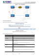
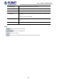
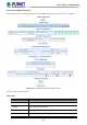
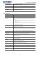
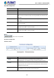
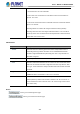
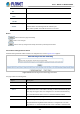
Table Of Contents
- 1. INTRODUCTION
- 2. INSTALLATION
- 3. SWITCH MANAGEMENT
- 4. WEB CONFIGURATION
- 4.1 Main Web page
- 4.2 System
- 4.2.1 Management
- 4.2.1.1 System Information
- 4.2.1.2 IP Configuration
- 4.2.1.3 IP Status
- 4.2.1.4 ARP Table
- 4.2.1.5 Users Configuration
- 4.2.1.6 Privilege Levels
- 4.2.1.7 NTP Configuration
- 4.2.1.7.1 System Time Correction Manually
- 4.2.1.8 Time Configuration
- 4.2.1.9 UPnP
- 4.2.1.10 DHCP Relay
- 4.2.1.11 DHCP Relay Statistics
- 4.2.1.12 CPU Load
- 4.2.1.13 System Log
- 4.2.1.14 Detailed Log
- 4.2.1.15 Remote Syslog
- 4.2.1.16 SMTP Configuration
- 4.2.1.17 Fault Alarm
- 4.2.1.18 Digital Input/Output
- 4.2.2 Simple Network Management Protocol
- 4.2.3 RMON
- 4.2.4 DHCP server
- 4.2.5 Remote Management
- 4.2.1 Management
- 4.3 Switching
- 4.3.1 Port Management
- 4.3.2 Link Aggregation
- 4.3.3 VLAN
- 4.3.3.1 VLAN Overview
- 4.3.3.2 IEEE 802.1Q VLAN
- 4.3.3.3 VLAN Port Configuration
- 4.3.3.4 VLAN Membership Status
- 4.3.3.5 VLAN Port Status
- 4.3.3.6 Private VLAN
- 4.3.3.7 Port Isolation
- 4.3.3.8 VLAN setting example:
- 4.3.3.9 MAC-based VLAN
- 4.3.3.10 IP Subnet-based VLAN Membership Configuration
- 4.3.3.11 Protocol-based VLAN
- 4.3.3.12 Protocol-based VLAN Membership
- 4.3.2.13 VLAN Translation
- 4.3.4 Spanning Tree Protocol
- 4.3.5 Multicast
- 4.3.6 MLD Snooping
- 4.3.7 MVR (Multicast VLAN Registration)
- 4.3.8 LLDP
- 4.3.9 MAC Address Table
- 4.3.10 Loop Protection
- 4.3.11 UDLD
- 4.3.12 GVRP
- 4.3.13 PTP
- 4.3.14 Link OAM
- 4.4 Quality of Service
- 4.4.2 Bandwidth Control
- 4.4.4.2 DSCP-based QoS
- 4.5 Security
- 4.6 Ring
- 4.7 Maintenance
- 5. COMMAND LINE MODE
- 6. SWITCH OPERATION
- 7. TROUBLESHOOTING
- APPENDIX A: Networking Connection
- APPENDIX B : GLOSSARY

User’s Manual of MGSD-10080F
366
* The transmission rate of the CCM PDU.
* Fault Cause cLOC is declared if no CCM PDU has been received within 3.5
periods - see 'cLOC'.
* Fault Cause cPeriod is declared if a CCM PDU has been received with different
period - see 'cPeriod'.
Selecting 300f/sec or 100f/sec will configure HW based CCM (if possible).
Selecting other frame rates will configure SW based CCM. In case of enable of
Continuity Check and Loss Measurement both implemented on SW based CCM,
'Frame Rate' has to be the same.
APS Protocol:
Object Description
• Enable
Automatic Protection Switching protocol information transportation based on
transmitting/receiving R-APS/L-APS PDU can be enabled/disabled. Must be
enabled to support ERPS/ELPS implementing APS. This is only valid with one
Peer MEP configured.
• Priority
The priority to be inserted as PCP bits in TAG (if any).
• Cast
Selection of APS PDU transmitted unicast or multi-cast. The unicast MAC will be
taken from the 'Unicast Peer MAC' configuration. Unicast is only valid for L-APS -
see 'Type'. The R-APS PDU is always transmitted with multi-cast MAC described
in G.8032.
• Type
R-APS: APS PDU is transmitted as R-APS - this is for ERPS.
L-APS: APS PDU is transmitted as L-APS - this is for ELPS.
• Last Octet
This is the last octet of the transmitted and expected RAPS multi-cast MAC. In
G.8031 (03/2010) a RAPS multi-cast MAC is defined as 01-19-A7-00-00-XX. In
current standard the value for this last octet is '01' and the usage of other values
is for further study.
Buttons
: Click to go to Fault Management page.
: Click to go to Performance Monitor page.