
User's Manual
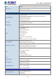
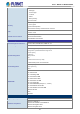
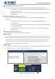
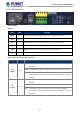
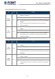
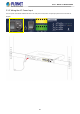
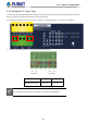
Table Of Contents
- 1. INTRODUCTION
- 2. INSTALLATION
- 3. SWITCH MANAGEMENT
- 4. WEB CONFIGURATION
- 4.1 Main Web page
- 4.2 System
- 4.2.1 Management
- 4.2.1.1 System Information
- 4.2.1.2 IP Configuration
- 4.2.1.3 IP Status
- 4.2.1.4 ARP Table
- 4.2.1.5 Users Configuration
- 4.2.1.6 Privilege Levels
- 4.2.1.7 NTP Configuration
- 4.2.1.7.1 System Time Correction Manually
- 4.2.1.8 Time Configuration
- 4.2.1.9 UPnP
- 4.2.1.10 DHCP Relay
- 4.2.1.11 DHCP Relay Statistics
- 4.2.1.12 CPU Load
- 4.2.1.13 System Log
- 4.2.1.14 Detailed Log
- 4.2.1.15 Remote Syslog
- 4.2.1.16 SMTP Configuration
- 4.2.1.17 Fault Alarm
- 4.2.1.18 Digital Input/Output
- 4.2.2 Simple Network Management Protocol
- 4.2.3 RMON
- 4.2.4 DHCP server
- 4.2.5 Remote Management
- 4.2.1 Management
- 4.3 Switching
- 4.3.1 Port Management
- 4.3.2 Link Aggregation
- 4.3.3 VLAN
- 4.3.3.1 VLAN Overview
- 4.3.3.2 IEEE 802.1Q VLAN
- 4.3.3.3 VLAN Port Configuration
- 4.3.3.4 VLAN Membership Status
- 4.3.3.5 VLAN Port Status
- 4.3.3.6 Private VLAN
- 4.3.3.7 Port Isolation
- 4.3.3.8 VLAN setting example:
- 4.3.3.9 MAC-based VLAN
- 4.3.3.10 IP Subnet-based VLAN Membership Configuration
- 4.3.3.11 Protocol-based VLAN
- 4.3.3.12 Protocol-based VLAN Membership
- 4.3.2.13 VLAN Translation
- 4.3.4 Spanning Tree Protocol
- 4.3.5 Multicast
- 4.3.6 MLD Snooping
- 4.3.7 MVR (Multicast VLAN Registration)
- 4.3.8 LLDP
- 4.3.9 MAC Address Table
- 4.3.10 Loop Protection
- 4.3.11 UDLD
- 4.3.12 GVRP
- 4.3.13 PTP
- 4.3.14 Link OAM
- 4.4 Quality of Service
- 4.4.2 Bandwidth Control
- 4.4.4.2 DSCP-based QoS
- 4.5 Security
- 4.6 Ring
- 4.7 Maintenance
- 5. COMMAND LINE MODE
- 6. SWITCH OPERATION
- 7. TROUBLESHOOTING
- APPENDIX A: Networking Connection
- APPENDIX B : GLOSSARY

User’s Manual of MGSD-10080F
26
2.1.2 LED Indicators
LED Definition
System
LED Color Function
PWR Green
Lights to indicate that the Managed Metro Switch is powered on by AC input.
DC1 Green
Lights to indicate that the Managed Metro Switch is powered on by DC1 input.
DC2 Green
Lights to indicate that the Managed Metro Switch is powered on by DC2 input.
Alarm Green
Lights to indicate that Managed Metro Switch AC/DC or port has failed.
Ring Green Lights to indicate that the ERPS Ring has been created successfully.
R.O Green Lights to indicate that Switch Ring Owner has been enabled.
Per 100/1000 SFP Interface (Port 1 to port 6)
LED Color Function
1000
LNK/ACT
Green
Lights:
To indicate the link through that port is successfully established at the speed of
1000Mbps.
Blink: To indicate that the switch is actively sending or receiving data over that port.
Off: If 1000 LNK/ACT LED is lit, it indicates the port is operating at 1000Mbps.
If 1000 LNK/ACT LED is off, it indicates that the port is link down or operating at
100Mbps.
100
LNK/ACT
Orange
Lights:
To indicate the link through that port is successfully established
at the speed of
100Mbps.
Blink: To indicate that the switch is actively sending or receiving data over that port.
Off: If 100 LNK/ACT LED is lit, it indicates the port is operating at 100Mbps
If 100 LNK/ACT LED is off, it indicates that the port is link down or operating at
1000Mbps.