
User's Manual
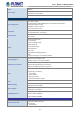
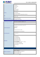
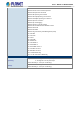
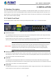
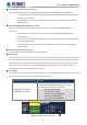
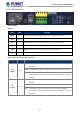
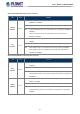
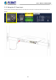
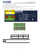
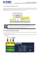
Table Of Contents
- 1. INTRODUCTION
- 2. INSTALLATION
- 3. SWITCH MANAGEMENT
- 4. WEB CONFIGURATION
- 4.1 Main Web page
- 4.2 System
- 4.2.1 Management
- 4.2.1.1 System Information
- 4.2.1.2 IP Configuration
- 4.2.1.3 IP Status
- 4.2.1.4 ARP Table
- 4.2.1.5 Users Configuration
- 4.2.1.6 Privilege Levels
- 4.2.1.7 NTP Configuration
- 4.2.1.7.1 System Time Correction Manually
- 4.2.1.8 Time Configuration
- 4.2.1.9 UPnP
- 4.2.1.10 DHCP Relay
- 4.2.1.11 DHCP Relay Statistics
- 4.2.1.12 CPU Load
- 4.2.1.13 System Log
- 4.2.1.14 Detailed Log
- 4.2.1.15 Remote Syslog
- 4.2.1.16 SMTP Configuration
- 4.2.1.17 Fault Alarm
- 4.2.1.18 Digital Input/Output
- 4.2.2 Simple Network Management Protocol
- 4.2.3 RMON
- 4.2.4 DHCP server
- 4.2.5 Remote Management
- 4.2.1 Management
- 4.3 Switching
- 4.3.1 Port Management
- 4.3.2 Link Aggregation
- 4.3.3 VLAN
- 4.3.3.1 VLAN Overview
- 4.3.3.2 IEEE 802.1Q VLAN
- 4.3.3.3 VLAN Port Configuration
- 4.3.3.4 VLAN Membership Status
- 4.3.3.5 VLAN Port Status
- 4.3.3.6 Private VLAN
- 4.3.3.7 Port Isolation
- 4.3.3.8 VLAN setting example:
- 4.3.3.9 MAC-based VLAN
- 4.3.3.10 IP Subnet-based VLAN Membership Configuration
- 4.3.3.11 Protocol-based VLAN
- 4.3.3.12 Protocol-based VLAN Membership
- 4.3.2.13 VLAN Translation
- 4.3.4 Spanning Tree Protocol
- 4.3.5 Multicast
- 4.3.6 MLD Snooping
- 4.3.7 MVR (Multicast VLAN Registration)
- 4.3.8 LLDP
- 4.3.9 MAC Address Table
- 4.3.10 Loop Protection
- 4.3.11 UDLD
- 4.3.12 GVRP
- 4.3.13 PTP
- 4.3.14 Link OAM
- 4.4 Quality of Service
- 4.4.2 Bandwidth Control
- 4.4.4.2 DSCP-based QoS
- 4.5 Security
- 4.6 Ring
- 4.7 Maintenance
- 5. COMMAND LINE MODE
- 6. SWITCH OPERATION
- 7. TROUBLESHOOTING
- APPENDIX A: Networking Connection
- APPENDIX B : GLOSSARY

User’s Manual of MGSD-10080F
25
■ 100/1000BASE-X SFP Slots (port 1 to port 6)
Each of the SFP (Small Form-factor Pluggable) slot supports dual-speed, 1000BASE-SX/LX or 100BASE-FX
- For 1000BASE-SX/LX SFP transceiver module: From 550 meters (multi-mode fiber) to 10/20/40/60/80/120
kilometers (single-mode fiber).
- For 100BASE-FX SFP transceiver module: From 2 kilometers (multi-mode fiber) to 20/40/60 kilometers
(single-mode fiber).
■ 100/1000/2500BASE-X SFP Slots (port 7 to port 8)
Each of the SFP (Small Form-factor Pluggable) slot supports triple-speed, 2500BASE-X,1000BASE-SX/LX or
100BASE-FX
- For 2500BASE-X SFP transceiver module: From 330 meters (multi-mode fiber) to 2/20kilometers
(single-mode fiber).
- For 1000BASE-SX/LX SFP transceiver module: From 550 meters (multi-mode fiber) to 10/20/40/60/80/120
kilometers (single-mode fiber).
- For 100BASE-FX SFP transceiver module: From 2 kilometers (multi-mode fiber) to 20/40/60 kilometers
(single-mode fiber).
■ Gigabit TP Interface(port 9 to port 10)
10/100/1000BASE-T Copper, RJ45 twisted-pair: Up to 100 meters.
■ Console Port
The console port is an RJ45 port connector. It is an interface for connecting a terminal directly. Through the console port, it
provides rich diagnostic information including IP Address setting, factory reset, port management, link status and system
setting. Users can use the attached DB9 to RJ45 console cable in the package and connect to the console port on the
device. After the connection, users can run any terminal emulation program (Hyper Terminal, ProComm Plus, Telix,
Winterm and so on) to enter the startup screen of the device.
■ Reset Button
In the middle of the front panel, the reset button is designed for rebooting the Managed Metro Switch without turning off and
on the power. The following is the summary table of Reset button function:
Reset Button Pressed and Released
Function
< 5 seconds: Switch Reboot
> 5 seconds: Factory Default
Reset the Managed Metro Switch to Factory Default
configuration. The Managed Metro Switch will then reboot
and load the default settings as shown below:
。 Default Username: admin
。 Default Password: admin
。 Default IP address: 192.168.0.100
。 Subnet mask: 255.255.255.0
。 Default Gateway:
192.168.0.254
Figure 2-2: MGSD-10080F Reset Button