
User's Manual
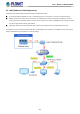
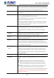
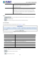
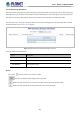
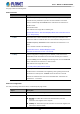
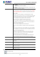
Table Of Contents
- 1. INTRODUCTION
- 2. INSTALLATION
- 3. SWITCH MANAGEMENT
- 4. WEB CONFIGURATION
- 4.1 Main Web page
- 4.2 System
- 4.2.1 Management
- 4.2.1.1 System Information
- 4.2.1.2 IP Configuration
- 4.2.1.3 IP Status
- 4.2.1.4 ARP Table
- 4.2.1.5 Users Configuration
- 4.2.1.6 Privilege Levels
- 4.2.1.7 NTP Configuration
- 4.2.1.7.1 System Time Correction Manually
- 4.2.1.8 Time Configuration
- 4.2.1.9 UPnP
- 4.2.1.10 DHCP Relay
- 4.2.1.11 DHCP Relay Statistics
- 4.2.1.12 CPU Load
- 4.2.1.13 System Log
- 4.2.1.14 Detailed Log
- 4.2.1.15 Remote Syslog
- 4.2.1.16 SMTP Configuration
- 4.2.1.17 Fault Alarm
- 4.2.1.18 Digital Input/Output
- 4.2.2 Simple Network Management Protocol
- 4.2.3 RMON
- 4.2.4 DHCP server
- 4.2.5 Remote Management
- 4.2.1 Management
- 4.3 Switching
- 4.3.1 Port Management
- 4.3.2 Link Aggregation
- 4.3.3 VLAN
- 4.3.3.1 VLAN Overview
- 4.3.3.2 IEEE 802.1Q VLAN
- 4.3.3.3 VLAN Port Configuration
- 4.3.3.4 VLAN Membership Status
- 4.3.3.5 VLAN Port Status
- 4.3.3.6 Private VLAN
- 4.3.3.7 Port Isolation
- 4.3.3.8 VLAN setting example:
- 4.3.3.9 MAC-based VLAN
- 4.3.3.10 IP Subnet-based VLAN Membership Configuration
- 4.3.3.11 Protocol-based VLAN
- 4.3.3.12 Protocol-based VLAN Membership
- 4.3.2.13 VLAN Translation
- 4.3.4 Spanning Tree Protocol
- 4.3.5 Multicast
- 4.3.6 MLD Snooping
- 4.3.7 MVR (Multicast VLAN Registration)
- 4.3.8 LLDP
- 4.3.9 MAC Address Table
- 4.3.10 Loop Protection
- 4.3.11 UDLD
- 4.3.12 GVRP
- 4.3.13 PTP
- 4.3.14 Link OAM
- 4.4 Quality of Service
- 4.4.2 Bandwidth Control
- 4.4.4.2 DSCP-based QoS
- 4.5 Security
- 4.6 Ring
- 4.7 Maintenance
- 5. COMMAND LINE MODE
- 6. SWITCH OPERATION
- 7. TROUBLESHOOTING
- APPENDIX A: Networking Connection
- APPENDIX B : GLOSSARY

User’s Manual of MGSD-10080F
219
The page includes the following fields:
LLDP Parameters
Object Description
• Tx Interval
The switch is periodically transmitting LLDP frames to its neighbors for having the
network discovery information up-to-date. The interval between each LLDP
frame is determined by the Tx Interval value. Valid values are restricted to 5 -
32768 seconds.
Default: 30 seconds
This attribute must comply with the following rule:
(Transmission Interval * Hold Time Multiplier) ≤65536, and Transmission Interval
>= (4 * Delay Interval)
• Tx Hold
Each LLDP frame contains information about how long the information in the
LLDP frame shall be considered valid. The LLDP information valid period is set to
Tx Hold multiplied by Tx Interval seconds. Valid values are restricted to 2 - 10
times.
TTL in seconds is based on the following rule:
(Transmission Interval * Holdtime Multiplier) ≤ 65536.
Therefore, the default TTL is 4*30 = 120 seconds.
• Tx Delay
If some configuration is changed (e.g. the IP address) a new LLDP frame is
transmitted, but the time between the LLDP frames will always be at least the
value of Tx Delay seconds. Tx Delay cannot be larger than 1/4 of the Tx Interval
value. Valid values are restricted to 1 - 8192 seconds.
This attribute must comply with the rule:
(4 * Delay Interval) ≤Transmission Interval
• Tx Reinit
When a port is disabled, LLDP is disabled or the switch is rebooted a LLDP
shutdown frame is transmitted to the neighboring units, signaling that the LLDP
information isn't valid anymore. Tx Reinit controls the amount of seconds
between the shutdown frame and a new LLDP initialization. Valid values are
restricted to 1 - 10 seconds.
LLDP Port Configuration
The LLDP port settings relate to the switch, as reflected by the page header.
Object Description
• Port
The switch port number of the logical LLDP port.
• Mode
Select LLDP mode.
Rx only The switch will not send out LLDP information, but LLDP
information from neighbor units is analyzed.
Tx only The switch will drop LLDP information received from neighbors, but
will send out LLDP information.