
User's Manual
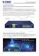
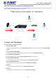
Table Of Contents
- 1. INTRODUCTION
- 2. INSTALLATION
- 3. SWITCH MANAGEMENT
- 4. WEB CONFIGURATION
- 4.1 Main Web page
- 4.2 System
- 4.2.1 Management
- 4.2.1.1 System Information
- 4.2.1.2 IP Configuration
- 4.2.1.3 IP Status
- 4.2.1.4 ARP Table
- 4.2.1.5 Users Configuration
- 4.2.1.6 Privilege Levels
- 4.2.1.7 NTP Configuration
- 4.2.1.7.1 System Time Correction Manually
- 4.2.1.8 Time Configuration
- 4.2.1.9 UPnP
- 4.2.1.10 DHCP Relay
- 4.2.1.11 DHCP Relay Statistics
- 4.2.1.12 CPU Load
- 4.2.1.13 System Log
- 4.2.1.14 Detailed Log
- 4.2.1.15 Remote Syslog
- 4.2.1.16 SMTP Configuration
- 4.2.1.17 Fault Alarm
- 4.2.1.18 Digital Input/Output
- 4.2.2 Simple Network Management Protocol
- 4.2.3 RMON
- 4.2.4 DHCP server
- 4.2.5 Remote Management
- 4.2.1 Management
- 4.3 Switching
- 4.3.1 Port Management
- 4.3.2 Link Aggregation
- 4.3.3 VLAN
- 4.3.3.1 VLAN Overview
- 4.3.3.2 IEEE 802.1Q VLAN
- 4.3.3.3 VLAN Port Configuration
- 4.3.3.4 VLAN Membership Status
- 4.3.3.5 VLAN Port Status
- 4.3.3.6 Private VLAN
- 4.3.3.7 Port Isolation
- 4.3.3.8 VLAN setting example:
- 4.3.3.9 MAC-based VLAN
- 4.3.3.10 IP Subnet-based VLAN Membership Configuration
- 4.3.3.11 Protocol-based VLAN
- 4.3.3.12 Protocol-based VLAN Membership
- 4.3.2.13 VLAN Translation
- 4.3.4 Spanning Tree Protocol
- 4.3.5 Multicast
- 4.3.6 MLD Snooping
- 4.3.7 MVR (Multicast VLAN Registration)
- 4.3.8 LLDP
- 4.3.9 MAC Address Table
- 4.3.10 Loop Protection
- 4.3.11 UDLD
- 4.3.12 GVRP
- 4.3.13 PTP
- 4.3.14 Link OAM
- 4.4 Quality of Service
- 4.4.2 Bandwidth Control
- 4.4.4.2 DSCP-based QoS
- 4.5 Security
- 4.6 Ring
- 4.7 Maintenance
- 5. COMMAND LINE MODE
- 6. SWITCH OPERATION
- 7. TROUBLESHOOTING
- APPENDIX A: Networking Connection
- APPENDIX B : GLOSSARY

User’s Manual of MGSD-10080F
17
1.4 Product Features
Physical Port
6 100/1000BASE-X SFP mini-GBIC slots (Port 1 to port 6)
2 100/1000/2500BASE-X mini-GBIC/SFP slots for SFP type auto detection(Port 7 to port 8)
2-Port 10/100/1000BASE-T Gigabit Ethernet RJ45 (Port 9 to port 10)
One RJ45 console interface for basic management and setup
Redundant Power System
Redundant Power System: 100V ~ 240V AC/Dual 36V ~ 60V DC
Active-active redundant power failure protection
Backup of catastrophic power failure on one supply
Fault tolerance and resilience.
Digital Input / Digital Output
2 Digital Input (DI)
2 Digital Output (DO)
Integrates sensors into auto alarm system
Transfer alarm to IP network via SNMP trap
Industrial Protocol
IEEE 1588v2 PTP (Precision Time Protocol) Transparent Clock mode
Hardware Design
-10 to 60 degrees C operating temperature for DC power input only
13-inch desktop size, 19-inch Rack-mountable
Relay alarm for port breakdown, power failure
Fanless design
Layer 2 Features
Prevents packet loss with back pressure (half-duplex) and IEEE 802.3x pause frame flow control (full-duplex)
High performance of Store-and-Forward architecture and runt/CRC filtering eliminate erroneous packets to optimize
the network bandwidth
Storm Control support
− Broadcast / Multicast / Unicast
Supports VLAN
− IEEE 802.1Q tagged VLAN
− Up to 4K VLANs groups, out of 4094 VLAN IDs
− Supports provider bridging (VLAN Q-in-Q, IEEE 802.1ad)
− Private VLAN Edge (PVE)
− Port Isolation
− MAC-based VLAN
− IP Subnet-based VLAN
− Protocol-based VLAN
− VLAN Translation
− Voice VLAN
− GVRP