
User's Manual
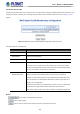
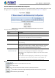
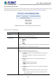
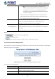
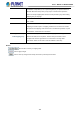
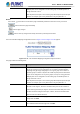
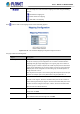
Table Of Contents
- 1. INTRODUCTION
- 2. INSTALLATION
- 3. SWITCH MANAGEMENT
- 4. WEB CONFIGURATION
- 4.1 Main Web page
- 4.2 System
- 4.2.1 Management
- 4.2.1.1 System Information
- 4.2.1.2 IP Configuration
- 4.2.1.3 IP Status
- 4.2.1.4 ARP Table
- 4.2.1.5 Users Configuration
- 4.2.1.6 Privilege Levels
- 4.2.1.7 NTP Configuration
- 4.2.1.7.1 System Time Correction Manually
- 4.2.1.8 Time Configuration
- 4.2.1.9 UPnP
- 4.2.1.10 DHCP Relay
- 4.2.1.11 DHCP Relay Statistics
- 4.2.1.12 CPU Load
- 4.2.1.13 System Log
- 4.2.1.14 Detailed Log
- 4.2.1.15 Remote Syslog
- 4.2.1.16 SMTP Configuration
- 4.2.1.17 Fault Alarm
- 4.2.1.18 Digital Input/Output
- 4.2.2 Simple Network Management Protocol
- 4.2.3 RMON
- 4.2.4 DHCP server
- 4.2.5 Remote Management
- 4.2.1 Management
- 4.3 Switching
- 4.3.1 Port Management
- 4.3.2 Link Aggregation
- 4.3.3 VLAN
- 4.3.3.1 VLAN Overview
- 4.3.3.2 IEEE 802.1Q VLAN
- 4.3.3.3 VLAN Port Configuration
- 4.3.3.4 VLAN Membership Status
- 4.3.3.5 VLAN Port Status
- 4.3.3.6 Private VLAN
- 4.3.3.7 Port Isolation
- 4.3.3.8 VLAN setting example:
- 4.3.3.9 MAC-based VLAN
- 4.3.3.10 IP Subnet-based VLAN Membership Configuration
- 4.3.3.11 Protocol-based VLAN
- 4.3.3.12 Protocol-based VLAN Membership
- 4.3.2.13 VLAN Translation
- 4.3.4 Spanning Tree Protocol
- 4.3.5 Multicast
- 4.3.6 MLD Snooping
- 4.3.7 MVR (Multicast VLAN Registration)
- 4.3.8 LLDP
- 4.3.9 MAC Address Table
- 4.3.10 Loop Protection
- 4.3.11 UDLD
- 4.3.12 GVRP
- 4.3.13 PTP
- 4.3.14 Link OAM
- 4.4 Quality of Service
- 4.4.2 Bandwidth Control
- 4.4.4.2 DSCP-based QoS
- 4.5 Security
- 4.6 Ring
- 4.7 Maintenance
- 5. COMMAND LINE MODE
- 6. SWITCH OPERATION
- 7. TROUBLESHOOTING
- APPENDIX A: Networking Connection
- APPENDIX B : GLOSSARY

User’s Manual of MGSD-10080F
169
•
You can modify each VLAN Translation mapping in the table using the following
buttons:
Edit: Edits the mapping row.
Delete: Deletes the mapping.
Add: Adds a new mapping.
Press
button to adds a new mapping and the screen is following appears.
Figure 4-3-2-22 : LAN Translation Mappings Configuration Page Screenshot
The page includes the following fields:
Object Description
• Group ID
The VLAN Translation mappings are organized into Groups, identified by the
Group ID. This way a port is configured to use a number of VLAN Translation
mappings easily by simply configuring it to use a given group. Then number of
possible groups in a switch is equal to the number of ports present in this switch.
A port can be configured to use any of the groups, but only one at any given time.
Multiple ports can be configured to use the same group. A valid Group ID is an
integer value from 1 to 10.
Note: By default, each port is set to use the group with Group ID equal to the port
number. For example, port #1 is by default set to use group with GID = 1.
• DIR
Indicates the direction of the VLAN Translation and it refers to the switch. The
direction can be 'Ingress', where the translation takes place on the VLAN ID of
frames entering the switch port, 'Egress', where the translation takes place on the
VLAN ID of frames exiting the switch port, or 'Both', where the translation takes
place on both of the above directions.
• VID
Indicates the VLAN ID of the mapping (i.e. 'source' VLAN). A valid VLAN ID
ranges from 1 to 4095.
• TVID
Indicates the translated VLAN ID to which a VLAN ID of a frame will be translated
to. A valid translated VLAN ID ranges from 1 to 4095.