User’s Manual of MGSD-10080F Trademarks Copyright © PLANET Technology Corp. 2021. Contents are subject to revision without prior notice. PLANET is a registered trademark of PLANET Technology Corp. All other trademarks belong to their respective owners.
User’s Manual of MGSD-10080F TABLE OF CONTENTS 1. INTRODUCTION ................................................................................................................. 10 1.1 Packet Contents ................................................................................................................................................ 10 1.2 Product Description .........................................................................................................................................
User’s Manual of MGSD-10080F 4.2.1.7 NTP Configuration ............................................................................................................................................... 63 4.2.1.7.1 System Time Correction Manually .................................................................................................................... 64 4.2.1.8 Time Configuration .........................................................................................................................
User’s Manual of MGSD-10080F 4.2.5 Remote Management ............................................................................................................................................... 114 4.3 Switching ......................................................................................................................................................... 116 4.3.1 Port Management ....................................................................................................................
User’s Manual of MGSD-10080F 4.3.4.9 Port Statistics ..................................................................................................................................................... 189 4.3.5 Multicast.................................................................................................................................................................... 190 4.3.5.1 IGMP Snooping ...................................................................................................
User’s Manual of MGSD-10080F 4.3.12.2 GVRP Port Configuration................................................................................................................................. 246 4.3.13 PTP .......................................................................................................................................................................... 247 4.3.13.1 PTP Configuration ........................................................................................................
User’s Manual of MGSD-10080F 4.5.2.1 Authentication Configuration .............................................................................................................................. 303 4.5.2.2 RADIUS ............................................................................................................................................................. 305 4.5.2.3 TACACS+ ..........................................................................................................................
User’s Manual of MGSD-10080F 4.7.1.2 Save Startup Config ........................................................................................................................................... 378 4.7.1.3 Configuration Download .................................................................................................................................... 378 4.7.1.4 Configuration Upload ..................................................................................................................
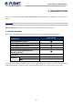
User’s Manual of MGSD-10080F 1. INTRODUCTION Thank you for purchasing PLANET L2+ Metro Ethernet Switch, the MGSD-10080F. The descriptions of this model are as follows: MGSD-10080F 6-Port 100/1000X SFP + 2-Port 1G/2.5G SFP + 2-Port 10/100/1000T Managed Metro Ethernet Switch “Managed Metro Switch” is used as an alternative name for the above model in this user’s manual. 1.1 Packet Contents Open the box of the Managed Metro Switch and carefully unpack it.
User’s Manual of MGSD-10080F 1.2 Product Description Multiple SFP Fiber Port Switch for Growing Long-Reach Networking of Enterprises, Telecoms and Campuses PLANET MGSD-10080F Managed Metro Ethernet Switch is equipped with advanced management functions and provides 6 100/1000Mbps dual speed SFP Fiber ports, 2 100/1000/2500Mbps SFP ports and 2 10/100/1000Mbps TP ports delivered in a rugged strong case.
User’s Manual of MGSD-10080F Redundant Ring, Fast Recovery for Critical Network Applications The MGSD-10080F supports redundant ring technology and features strong, rapid self-recovery capability to prevent interruptions and external intrusions. It incorporates advanced ITU-T G.8032 ERPS (Ethernet Ring Protection Switching) technology, Spanning Tree Protocol (802.1s MSTP) into customer’s network to enhance system reliability and uptime in various environments.
User’s Manual of MGSD-10080F Digital Input and Digital Output for External Alarm The MGSD-10080F supports Digital Input, and Digital Output on the front panel. The external alarm offers technicians the ability to use Digital Input to detect, and log external device status (such as door intrusion detector) for the alarm as Digital Output could be used to alarm if the MGSD-10080F has port link down, link up or power failure.
User’s Manual of MGSD-10080F Cost-effective IPv6 Managed Gigabit Switch Solution for Metro Ethernet To fulfill the demand for ISP to build the IPv6 (Internet Protocol version 6) network infrastructure speedily, the MGSD-10080F supports both IPv4 and IPv6 management functions. It can work with original IPv4 network structure and also support the new IPv6 network structure.
User’s Manual of MGSD-10080F Powerful Security The MGSD-10080F offers comprehensive Layer 2 to Layer 4 Access Control List (ACL) for enforcing security to the edge. It can be used to restrict network access by denying packets based on source and destination IP address, TCP/UDP ports or defined typical network applications. Its protection mechanism also comprises 802.1x Port-based user authentication. With the private VLAN function, communication between edge ports can be prevented to ensure user privacy.
User’s Manual of MGSD-10080F 1588 Time Protocol for Industrial Computing Networks The MGSD-10080F is ideal for telecom and Carrier Ethernet applications, supporting MEF service delivery and timing over packet solutions for IEEE 1588 and synchronous Ethernet. 1.3 How to Use This Manual This User’s Manual is structured as follows: Section 2, INSTALLATION The section explains the functions of the Managed Metro Switch and how to physically install the Managed Metro Switch.
User’s Manual of MGSD-10080F 1.
User’s Manual of MGSD-10080F Supports Spanning Tree Protocol − STP, IEEE 802.1D Spanning Tree Protocol − RSTP, IEEE 802.1w Rapid Spanning Tree Protocol − MSTP, IEEE 802.1s Multiple Spanning Tree Protocol, spanning tree by VLAN − BPDU Filtering/BPDU Guard Supports Link Aggregation − 802.
User’s Manual of MGSD-10080F Access Control List − IP-based Access Control List (ACL) − MAC-based Access Control List Source MAC/IP address binding DHCP Snooping to filter un-trusted DHCP messages Dynamic ARP Inspection discards ARP packets with invalid MAC address to IP address binding IP Source Guard prevents IP spoofing attacks IP address access management to prevent unauthorized intruder Management IPv4 and IPv6 dual stack management Switch Management Interfaces - Web switch mana
User’s Manual of MGSD-10080F 1.5 Product Specifications Product MGSD-10080F Hardware Specifications 6 1000BASE-SX/LX/BX SFP interfaces, from port 1 to port 6 SFP Fiber Optic Ports Compatible with 100BASE-FX SFP.
User’s Manual of MGSD-10080F Flash Flow Control Jumbo Frame 64Mbytes IEEE 802.
User’s Manual of MGSD-10080F - IP Address - Ethertype - Protocol Type - VLAN ID - DSCP - 802.1p Priority Up to 123 entries Port Security Security IP source guard Dynamic ARP inspection Command line authority control based on user level AAA RADIUS client TACACS+ client IEEE 802.
User’s Manual of MGSD-10080F IEEE 802.3bz 2.5GBASE-X IEEE 802.3x flow control and back pressure IEEE 802.3ad port trunk with LACP IEEE 802.1D Spanning Tree Protocol IEEE 802.1w Rapid Spanning Tree Protocol IEEE 802.1s Multiple Spanning Tree Protocol IEEE 802.1p Class of Service IEEE 802.1Q VLAN tagging IEEE 802.1ad Q-in-Q VLAN stacking IEEE 802.1X Port Authentication Network Control IEEE 802.1ab LLDP IEEE 802.3ah OAM IEEE 802.
User’s Manual of MGSD-10080F 2. INSTALLATION 2.1 Hardware Description This section describes the hardware features and installation of the Managed Metro Switch on the desktop or rack mount. For easier management and control of the Managed Metro Switch, familiarize yourself with its display indicators, and ports. Front panel illustrations in this chapter display the unit LED indicators. Before connecting any network device to the Managed Metro Switch, please read this chapter completely. 2.1.
User’s Manual of MGSD-10080F ■ 100/1000BASE-X SFP Slots (port 1 to port 6) Each of the SFP (Small Form-factor Pluggable) slot supports dual-speed, 1000BASE-SX/LX or 100BASE-FX - For 1000BASE-SX/LX SFP transceiver module: From 550 meters (multi-mode fiber) to 10/20/40/60/80/120 kilometers (single-mode fiber). - For 100BASE-FX SFP transceiver module: From 2 kilometers (multi-mode fiber) to 20/40/60 kilometers (single-mode fiber).
User’s Manual of MGSD-10080F 2.1.2 LED Indicators LED Definition System LED Color Function PWR Green Lights to indicate that the Managed Metro Switch is powered on by AC input. DC1 Green Lights to indicate that the Managed Metro Switch is powered on by DC1 input. DC2 Green Lights to indicate that the Managed Metro Switch is powered on by DC2 input. Alarm Green Lights to indicate that Managed Metro Switch AC/DC or port has failed.
User’s Manual of MGSD-10080F Per 100/1000/2500 SFP Interface (Port 7 to port 8) LED Color Function Lights: To indicate the link through that port is successfully established at the speed of 1000Mbps or 2500Mbps. Blink: To indicate that the switch is actively sending or receiving data over that port. 1G/2.5G LNK/ACT Green Off: If 1G/2.5G LNK/ACT LED is lit, it indicates the port is operating at 1000Mbps or 2500Mbps. If 1G/2.
User’s Manual of MGSD-10080F 2.1.2 Wiring the AC Power Input The front panel of the MGSD-10080F indicates an AC inlet power socket, which accepts input power from 100 to 240V AC, 50/60Hz.
User’s Manual of MGSD-10080F 2.1.3 Wiring the DC Power Input The Front Panel of the Managed Metro Switch indicates a DC inlet power socket and consists of one terminal block connector within 6 contacts. Please follow the steps below to insert the power wire. 1. Insert positive/negative DC power wires into the contacts 1 and 2 for DC POWER 1, or 5 and 6 for DC POWER 2. 2. Tighten the wire-clamp screws for preventing the wires from loosening.
User’s Manual of MGSD-10080F 2.1.4 Wiring the Fault Alarm Contact The fault alarm contacts are in the middle (3 & 4) of the terminal block connector as the picture shows below. Inserting the wires, the Managed Metro Switch will detect the fault status of the power failure, or port link failure (available for managed model). The following illustration shows an application example for wiring the fault alarm contacts. Insert the wires into the fault alarm contacts 1.
User’s Manual of MGSD-10080F 2. Tighten the wire-clamp screws for preventing the wires from loosening. 1 DI0 2 3 4 5 6 DI1 DO0 DO1 GND GND Figure 2-4: 6-pin Terminal Block for DI and DO Wiring Input 3. There are two Digital Input groups for you to monitor two different devices. The following topology shows how to wire DI0 and DI1.
User’s Manual of MGSD-10080F 4. There are two Digital Output groups for you to sense Managed Metro Switch port failure or power failure and issue a high or low signal to external device. The following topology shows how to wire DO0 and DO1.
User’s Manual of MGSD-10080F 2.2 Installing the Managed Metro Switch This section describes how to install your Managed Metro Switch and make connections to the Managed Metro Switch. Please read the following topics and perform the procedures in the order being presented. To install your Managed Metro Switch on a desktop or shelf, simply complete the following steps. In this paragraph, we will describe how to install the Managed Metro Switch and the installation points attended to it. 2.2.
User’s Manual of MGSD-10080F 2.2.2 Rack Mounting To install the Managed Metro Switch in a 19-inch standard rack, please follow the instructions described below. Step 1: Place the Managed Metro Switch on a hard flat surface, with the front panel positioned towards the front side. Step 2: Attach the rack-mount bracket to each side of the Managed Metro Switch with supplied screws attached to the package. Figure 2-8 shows how to attach brackets to one side of the Managed Metro Switch.
User’s Manual of MGSD-10080F 2.3 Cabling 10/100/1000BASE-T All 10/100/1000BASE-T ports come with auto-negotiation capability. They automatically support 1000BASE-T, 100BASE-TX and 10BASE-T networks. Users only need to plug a working network device into one of the 10/100/1000BASE-T ports, and then turn on the Managed Metro Switch. The port will automatically run at 10Mbps, 20Mbps, 100Mbps or 200Mbps and 1000Mbps or 2000Mbps after negotiating with the connected device.
User’s Manual of MGSD-10080F 2.3.1 Installing the SFP Transceiver The sections describe how to insert an SFP transceiver into an SFP slot. The SFP transceivers are hot-pluggable and hot-swappable. You can plug in and out the transceiver to/from any SFP port without having to power down the Managed Metro Switch as Figure 2-10 shows below: Figure 2-10: Plugging in the SFP Transceiver Approved PLANET SFP Transceivers PLANET Managed Metro Switch supports both single mode and multi-mode SFP transceivers.
User’s Manual of MGSD-10080F Gigabit Ethernet Transceiver (1000BASE-X SFP) Model DDM Speed (Mbps) Connector Interface Fiber Mode Distance MGB-GT -- 1000 Copper -- 100m -- 0 ~ 60 ℃ MGB-SX(V2) YES 1000 LC Multi Mode 550m 850nm 0 ~ 60 ℃ MGB-SX2(V2) YES 1000 LC Multi Mode 2km 1310nm 0 ~ 60 ℃ MGB-LX(V2) YES 1000 LC Single Mode 20km 1310nm 0 ~ 60 ℃ MGB-L40 YES 1000 LC Single Mode 40km 1310nm 0 ~ 60 ℃ MGB-L80 YES 1000 LC Single Mode 80km 1550nm 0 ~ 60 ℃ MGB-L12
User’s Manual of MGSD-10080F 2.3.2 Removing the SFP Transceiver 1. Make sure there is no network activity by checking with the network administrator, or through the management interface of the switch/converter (if available) to disable the port in advance. 2. Remove the Fiber Optic Cable gently. 3. Lift up the lever of the MFB/MGB series SFP module and turn it to a horizontal position. 4. Pull out the module gently through the lever.
User’s Manual of MGSD-10080F 3. SWITCH MANAGEMENT This chapter explains the methods that you can use to configure management access to the Managed Metro Switch. It describes the types of management applications and the communication and management protocols that deliver data between your management device (workstation or personal computer) and the system. It also contains information about port connection options.
User’s Manual of MGSD-10080F 3.2 Management Access Overview The Managed Metro Switch gives you the flexibility to access and manage it using any or all of the following methods: Remote Telnet Interface Web browser Interface An external SNMP-based network management application The remote Telnet and Web browser interfaces are embedded in the Managed Metro Switch software and are available for immediate use. Each of these management methods has their own advantages.
User’s Manual of MGSD-10080F 3.3 CLI Mode Management There are two ways for CLI mode management, one is remote telnet and the other operated from console port. Remote telnet is an IP-based protocol and console port is for user to operate the Managed Metro Switch locally only; however, their operations are the same. The command line user interface is for performing system administration, such as displaying statistics or changing option settings.
User’s Manual of MGSD-10080F You can change these settings, if desired, after you log on. This management method is often preferred because you can remain connected and monitor the system during system reboots. Also, certain error messages are sent to the serial port, regardless of the interface through which the associated action was initiated. A Macintosh or PC attachment can use any terminal-emulation program for connecting to the terminal serial port.
User’s Manual of MGSD-10080F 3.4 Web Management The Managed Metro Switch offers management features that allow users to manage the Managed Metro Switch from anywhere on the network through a standard browser such as Microsoft Internet Explorer. After you set up your IP address for the Managed Metro Switch, you can access the Managed Metro Switch’s Web interface applications directly in your Web browser by entering the IP address of the Managed Metro Switch.
User’s Manual of MGSD-10080F 3.5 SNMP-based Network Management You can use an external SNMP-based application to configure and manage the Managed Metro Switch, such as SNMP Network Manager, HP Openview Network Node Management (NNM) or What’s Up Gold. This management method requires the SNMP agent on the Managed Metro Switch and the SNMP Network Management Station to use the same community string.
User’s Manual of MGSD-10080F If there are two LAN cards or above in the same administrator PC, choose a different LAN card by using the “Select Adapter” tool. 3. Press the “Refresh” button for the currently connected devices in the discovery list as the screen is shown as follows. Figure 3-6: Planet Smart Discovery Utility Screen 1. This utility shows all the necessary information from the devices, such as MAC Address, Device Name, firmware version and Device IP Subnet address.
User’s Manual of MGSD-10080F 4. WEB CONFIGURATION This section introduces the configuration and functions of the Web-based management. About Web-based Management The Managed Metro Switch offers management features that allow users to manage the Managed Metro Switch from anywhere on the network through a standard browser such as Microsoft Internet Explorer.
User’s Manual of MGSD-10080F Figure 4-1-2: Login Screen Default User name: admin Default Password: admin After entering the username and password, the main screen appears as Figure 4-1-3. Figure 4-1-3: Web Main Screen of Managed Metro Switch Now, you can use the Web management interface to continue the switch management or manage the Managed Metro Switch by Web interface. The Switch Menu on the left of the web page let you access all the commands and statistics the Managed Metro Switch provides.
User’s Manual of MGSD-10080F For security reason, please change and memorize the new password after this first setup. Only accept command in lowercase letter under web interface.
User’s Manual of MGSD-10080F 4.1 Main Web page The Managed Metro Switch provides a Web-based browser interface for configuring and managing it. This interface allows you to access the Managed Metro Switch using the Web browser of your choice. This chapter describes how to use the Managed Metro Switch’s Web browser interface to configure and manage it.
User’s Manual of MGSD-10080F Main Menu Using the onboard web agent, you can define system parameters, manage and control the Managed Metro Switch, and all its ports, or monitor network conditions. Via the Web-Management, the administrator can set up the Managed Metro Switch by selecting the functions those listed in the Main Function. The screen in Figure 4-1-5 appears.
User’s Manual of MGSD-10080F 4.2 System Use the System menu items to display and configure basic administrative details of the Managed Metro Switch. Under the System, the following topics are provided to configure and view the system information. This section has the following items: ■ System Information The Managed Metro Switch system information is provided here. ■ IP Configuration Configure the IPv4/IPv6 interface and IP routes of the Managed Metro Switch on this page.
User’s Manual of MGSD-10080F 4.2.1 Management 4.2.1.1 System Information The System Infomation page provides information for the current device information. System Information page helps a switch administrator to identify the hardware MAC address, software version and system uptime. The screen in Figure 4-2-1 appears.
User’s Manual of MGSD-10080F 4.2.1.2 IP Configuration The IP Configuration includes the IP Configuration, IP Interface and IP Routes. The configured column is used to view or change the IP configuration. The maximum number of interfaces supported is 128 and the maximum number of routes is 32. The screen in Figure 4-2-2 appears. Figure 4-2-2: IP Configuration Page Screenshot The current column is used to show the active IP configuration.
User’s Manual of MGSD-10080F client devices on the network. • IP Interface Delete Select this option to delete an existing IP interface. VLAN The VLAN associated with the IP interface. Only ports in this VLAN will be able to access the IP interface. This field is only available for input when creating a new interface. IPv4 Enabled Enable the DHCP client by checking this box. DHCP Fallback The number of seconds for trying to obtain a DHCP lease.
User’s Manual of MGSD-10080F Buttons : Click to add a new IP interface. A maximum of 128 interfaces are supported. : Click to add a new IP route. A maximum of 32 routes are supported. : Click to apply changes. : Click to undo any changes made locally and revert to previously saved values.
User’s Manual of MGSD-10080F 4.2.1.3 IP Status IP Status displays the status of the IP protocol layer. The status is defined by the IP interfaces, the IP routes and the neighbor cache (ARP cache) status. The screen in Figure 4-2-3 appears. Figure 4-2-3: IP Status Page Screenshot The page includes the following fields: Object Description • IP Interfaces • IPv4/v6 Routes • Neighbor Cache Interface The name of the interface. Type The address type of the entry. This may be LINK or IPv4.
User’s Manual of MGSD-10080F 4.2.1.4 ARP Table This page provides an overview of the current ARP table, also allow to configure Aging time setting on this page. After setup is completed, press the “Apply” button to take effect, the screen in Figure 4-2-4 appears. Figure 4-2-4: ARP Table Configuration Page Screenshot The page includes the following fields: Object Description • Disable Automatic Aging Provide disable MAC learning function by enable this function.
User’s Manual of MGSD-10080F 4.2.1.5 Users Configuration This page provides an overview of the current users. Currently the only way to login as another user on the web server is to close and reopen the browser. After setup is completed, press the “Apply” button to take effect. Please login web interface with new user name and password; the screen in Figure 4-2-5 appears.
User’s Manual of MGSD-10080F Figure 4-2-6: Add / Edit User Configuration Page Screenshot The page includes the following fields: Object Description • Username A string identifying the user name that this entry should belong to. The allowed string length is 1 to 31. The valid user name is a combination of letters, numbers and underscores. • Password The password of the user. The allowed string length is 0 to 31. • Password (again) Please enter the user’s new password here again to confirm.
User’s Manual of MGSD-10080F Once the new user is added, the new user entry is shown on the Users Configuration page. Figure 4-2-7: User Configuration Page Screenshot If you forget the new password after changing the default password, please press the “Reset” button on the front panel of the Managed Metro Switch for over 5 seconds and then release it. The current setting including VLAN will be lost and the Managed Metro Switch will restore to the default mode.
User’s Manual of MGSD-10080F 4.2.1.6 Privilege Levels This page provides an overview of the privilege levels. After setup is completed, please press the “Apply” button to take effect. Please login web interface with new user name and password and the screen in Figure 4-2-8 appears.
User’s Manual of MGSD-10080F The page includes the following fields: Object Description • Group Name The name identifying the privilege group. In most cases, a privilege level group consists of a single module (e.g. LACP, RSTP or QoS), but a few of them contain more than one. The following description defines these privilege level groups in details: System: Contact, Name, Location, Timezone, Log.
User’s Manual of MGSD-10080F 4.2.1.7 NTP Configuration Configure NTP on this page. NTP is an acronym for Network Time Protocol, a network protocol for synchronizing the clocks of computer systems. NTP uses UDP (data grams) as transport layer. You can specify NTP Servers. The NTP Configuration screen in Figure 4-2-9 appears. Figure 4-2-9: NTP Configuration Page Screenshot The page includes the following fields: Object Description • Mode Indicates the NTP mode operation.
User’s Manual of MGSD-10080F 4.2.1.7.1 System Time Correction Manually Configure NTP on this page. NTP is an acronym for Network Time Protocol, a network protocol for synchronizing the clocks of computer systems. NTP uses UDP (data grams) as transport layer. You can specify NTP Servers. The NTP Configuration screen in Figure 4-2-10 appears.
User’s Manual of MGSD-10080F 4.2.1.8 Time Configuration Configure Time Zone on this page. A Time Zone is a region that has a uniform standard time for legal, commercial, and social purposes. It is convenient for areas in close commercial or other communication to keep the same time, so time zones tend to follow the boundaries of countries and their subdivisions.
User’s Manual of MGSD-10080F Daylight Saving Time duration to repeat the configuration every year. Select 'Non-Recurring' and configure the Daylight Saving Time duration for single time configuration. ( Default: Disabled ). • Start Time Settings • Week - Select the starting week number. • Day - Select the starting day. • Month - Select the starting month. • Hours - Select the starting hour. • Minutes - Select the starting minute. • End Time Settings • Week - Select the ending week number.
User’s Manual of MGSD-10080F 4.2.1.9 UPnP Configure UPnP on this page. UPnP is an acronym for Universal Plug and Play. The goals of UPnP are to allow devices to connect seamlessly and to simplify the implementation of networks in the home (data sharing, communications, and entertainment) and in corporate environments for simplified installation of computer components. The UPnP Configuration screen in Figure 4-2-12 appears.
User’s Manual of MGSD-10080F • Static VLAN Interface ID The index of the specific IP VLAN interface. It will only be applied when IP Addressing Mode is static. Valid configurable values ranges from 1 to 4095. Default value is 1. Buttons : Click to apply changes : Click to undo any changes made locally and revert to previously saved values.
User’s Manual of MGSD-10080F 4.2.1.10 DHCP Relay Configure DHCP Relay on this page. DHCP Relay is used to forward and transfer DHCP messages between the clients and the server when they are not on the same subnet domain. The DHCP option 82 enables a DHCP relay agent to insert specific information into a DHCP request packets when forwarding client DHCP packets to a DHCP server and remove the specific information from a DHCP reply packets when forwarding server DHCP packets to a DHCP client.
User’s Manual of MGSD-10080F Enabled: Enable DHCP relay information mode operation. When enabling DHCP relay information mode operation, the agent inserts specific information (option82) into a DHCP message when forwarding to DHCP server and removing it from a DHCP message when transferring to DHCP client. It only works under DHCP relay operation mode enabled. Disabled: Disable DHCP relay information mode operation. • Relay Information Policy Indicates the DHCP relay information option policy.
User’s Manual of MGSD-10080F 4.2.1.11 DHCP Relay Statistics This page provides statistics for DHCP relay. The DHCP Relay Statistics screen in Figure 4-2-14 appears. Figure 4-2-14: DHCP Relay Statistics Page Screenshot The page includes the following fields: Server Statistics Object Description • Transmit to Server The packets number that relayed from client to server. • Transmit Error The packets number that erroneously sent packets to clients.
User’s Manual of MGSD-10080F Client Statistics Object Description • Transmit to Client The packets number that relayed packets from server to client. • Transmit Error The packets number that erroneously sent packets to servers. • Receive from Client The packets number that received packets from server. • Receive Agent Option The packets number that received packets with relay agent information option.
User’s Manual of MGSD-10080F 4.2.1.12 CPU Load This page displays the CPU load, using an SVG graph. The load is measured as average over the last 100ms, 1 sec and 10 seconds intervals. The last 120 samples are graphed, and the last numbers are displayed as text as well. In order to display the SVG graph, your browser must support the SVG format. Consult the SVG Wiki for more information on browser support.
User’s Manual of MGSD-10080F 4.2.1.13 System Log The Managed Metro Switch system log information is provided here. The System Log screen in Figure 4-2-16 appears. Figure 4-2-16: System Log Page Screenshot The page includes the following fields: Object Description • ID The ID (>= 1) of the system log entry. • Level The level of the system log entry. The following level types are supported: Info: Information level of the system log. Warning: Warning level of the system log.
User’s Manual of MGSD-10080F : Updates the system log entries, ending at the last entry currently displayed. : Updates the system log entries, starting from the last entry currently displayed. : Updates the system log entries, ending at the last available entry ID. 4.2.1.14 Detailed Log The Managed Metro Switch system detailed log information is provided here. The Detailed Log screen in Figure 4-2-17 appears.
User’s Manual of MGSD-10080F 4.2.1.15 Remote Syslog Configure remote syslog on this page. The Remote Syslog screen in Figure 4-2-18 appears. Figure 4-2-18: Remote Syslog Page Screenshot The page includes the following fields: Object Description • Mode Indicates the server mode operation. When the mode operation is enabled, the syslog message will send out to syslog server.
User’s Manual of MGSD-10080F 4.2.1.16 SMTP Configuration This page facilitates an SMTP Configuration on the switch. The SMTP Configure screen in Figure 4-2-19 appears. Figure 4-2-19: SMTP Configuration Page Screenshot The page includes the following fields: Object Description • SMTP Mode Controls whether SMTP is enabled on this switch. • SMTP Server Type the SMTP server name or the IP address of the SMTP server. • SMTP Port Set port number of SMTP service.
User’s Manual of MGSD-10080F 4.2.1.17 Fault Alarm The Managed Metro Switch supports a Fault Alarm feature which can alert the users when there is something wrong with the switches. With this ideal feature, the users would not have to waste time finding where the problem is. It will help to save time and human resource. This page facilitates an update of the firmware controlling the switch. The Web Firmware Upgrade screen in Figure 4-2-20 appears.
User’s Manual of MGSD-10080F 4.2.1.18 Digital Input/Output Digital Input allows user to log external device (such as industrial cooler) dead or alive or something else. System will log a user customized message into system log and syslog, and issue SNMP trap or issue an alarm E-mail. Digital Output allows user to monitor the switch port and power, and let system issue a high or low signal to an external device (such as alarm) when the monitor port or power has failed.
User’s Manual of MGSD-10080F The page includes the following fields: Object Description • Enable Check the Enable checkbox to enable Digital Input function. Uncheck the Enable checkbox to disable Digital Input function. • DI Condition As Digital Input: Allows user to select High to Low or Low to High. This means a signal received by system is from High to Low or From Low to High. It will trigger an action that logs a customize message or issue the message from the switch.
User’s Manual of MGSD-10080F Low signal to an external device such as an alarm. • Power Alarm Allows user to choose which power module that needs to be monitored. • Port Fail Alarm Allows user to choose which port that needs to be monitored. Buttons : Click to save changes. : Click to undo any changes made locally and revert to previously saved values.
User’s Manual of MGSD-10080F 4.2.2 Simple Network Management Protocol 4.2.2.1 SNMP Overview The Simple Network Management Protocol (SNMP) is an application layer protocol that facilitates the exchange of management information between network devices. It is part of the Transmission Control Protocol/Internet Protocol (TCP/IP) protocol suite. SNMP enables network administrators to manage network performance, find and solve network problems, and plan for network growth.
User’s Manual of MGSD-10080F default communities are: 。 Write = private 。 Read = public Use the SNMP Menu to display or configure the Managed Metro Switch 's SNMP function. This section has the following items: System Configuration Configure SNMP on this page. System Information The system information is provided here. SNMP Trap Configuration Configure SNMP trap on this page. Trap Source Configuration SNMP trap source configurations.
User’s Manual of MGSD-10080F 4.2.2.3 SNMP System Information The switch system information is provided here. The SNMP System Information screen in Figure 4-2-2-3 appears. Figure 4-2-2-3: System Information Configuration Page Screenshot The page includes the following fields: Object Description • System Contact The textual identification of the contact person for this managed node, together with information on how to contact this person.
User’s Manual of MGSD-10080F 4.2.2.4 SNMP Trap Configuration Configure SNMP trap on this page. The SNMP Trap Configuration screen in Figure 4-2-2-4 appears. Click ‘Add New Entry” and then the SNMP Trap Configuration page appears. Figure 4-2-2-4: SNMP Trap Configuration Page Screenshot The page includes the following fields: Object Description • Trap Config Indicates which trap Configuration's name for configuring.
User’s Manual of MGSD-10080F • Trap Community Indicates the community access string when send SNMP trap packet. The allowed string length is 0 to 255, and the allowed content is the ASCII characters from 33 to 126. • Trap Destination Indicates the SNMP trap destination address. Address • Trap Destination Port Indicates the SNMP trap destination port. SNMP Agent will send SNMP message via this port, the port range is 1~65535. • Trap Inform Mode Indicates the SNMP trap inform mode operation.
User’s Manual of MGSD-10080F 4.2.2.5 SNMP Trap Source Configuration This page provides SNMP trap source configurations. A trap is sent for the given trap source if at least one filter with filter type included matches the filter, and no filters with filter type excluded matches. Figure 4-2-2-5: SNMP Trap Source Configuration Page Screenshot Click “Add New Entry” to add a new entry. The maximum entry count is 32.
User’s Manual of MGSD-10080F • Subset OID The subset OID for the entry. The value should depend on the what kind of trap name. For example, the ifIdex is the subset OID of linkUp and linkDown. A valid subset OID is one or more digital number(0-4294967295) or asterisk(*) which are separated by dots(.). The first character must not begin with asterisk(*) and the maximum of OID count must not exceed 128. Buttons : Click to add a new community entry.
User’s Manual of MGSD-10080F 4.2.2.6 SNMPv3 Communities Configure SNMPv3 communities table on this page. The entry index key is Community. The SNMPv3 Communities screen in Figure 4-2-2-7 appears. Figure 4-2-2-7: SNMPv3 Communities Configuration Page Screenshot The page includes the following fields: Object Description • Delete Check to delete the entry. It will be deleted during the next save. • Community Indicates the community access string to permit access to SNMPv3 agent.
User’s Manual of MGSD-10080F 4.2.2.7 SNMPv3 Users Configure SNMPv3 users table on this page. The entry index keys are Engine ID and User Name. The SNMPv3 Users screen in Figure 4-2-2-8 appears. Figure 4-2-2-8: SNMPv3 Users Configuration Page Screenshot The page includes the following fields: Object Description • Delete Check to delete the entry. It will be deleted during the next save. • Engine ID An octet string identifying the engine ID that this entry should belong to.
User’s Manual of MGSD-10080F SHA: An optional flag to indicate that this user using SHA authentication protocol. The value of security level cannot be modified if entry already exist. That means must first ensure that the value is set correctly. • Authentication Password A string identifying the authentication pass phrase. For MD5 authentication protocol, the allowed string length is 8 to 32. For SHA authentication protocol, the allowed string length is 8 to 40.
User’s Manual of MGSD-10080F 4.2.2.8 SNMPv3 Groups Configure SNMPv3 groups table on this page. The entry index keys are Security Model and Security Name. The SNMPv3 Groups screen in Figure 4-2-2-9 appears. Figure 4-2-2-9: SNMPv3 Groups Configuration Page Screenshot The page includes the following fields: Object Description • Delete Check to delete the entry. It will be deleted during the next save. • Security Model Indicates the security model that this entry should belong to.
User’s Manual of MGSD-10080F 4.2.2.9 SNMPv3 Views Configure SNMPv3 views table on this page. The entry index keys are View Name and OID Subtree. The SNMPv3 Views screen in Figure 4-2-2-10 appears. Figure 4-2-2-10: SNMPv3 Views Configuration Page Screenshot The page includes the following fields: Object Description • Delete Check to delete the entry. It will be deleted during the next save. • View Name A string identifying the view name that this entry should belong to.
User’s Manual of MGSD-10080F 4.2.2.10 SNMPv3 Access Configure SNMPv3 accesses table on this page. The entry index keys are Group Name, Security Model and Security Level. The SNMPv3 Access screen in Figure 4-2-2-11 appears. Figure 4-2-2-11: SNMPv3 Accesses Configuration Page Screenshot The page includes the following fields: Object Description • Delete Check to delete the entry. It will be deleted during the next save. • Group Name A string identifying the group name that this entry should belong to.
User’s Manual of MGSD-10080F 4.2.3 RMON RMON is the most important expansion of the standard SNMP. RMON is a set of MIB definitions, used to define standard network monitor functions and interfaces, enabling the communication between SNMP management terminals and remote monitors. RMON provides a highly efficient method to monitor actions inside the subnets. MID of RMON consists of 10 groups.
User’s Manual of MGSD-10080F a higher-layer protocol. InDiscards: The number of inbound packets that are discarded even the packets are normal. InErrors: The number of inbound packets that contains errors preventing them from being deliverable to a higher-layer protocol. InUnknownProtos: the number of the inbound packets that is discarded because of the unknown or un-support protocol. OutOctets: The number of octets transmitted out of the interface, including framing characters.
User’s Manual of MGSD-10080F 4.2.3.2 RMON Alarm Status This page provides an overview of RMON Alarm entries. Each page shows up to 99 entries from the Alarm table, default being 20, selected through the "entries per page" input field. When first visited, the web page will show the first 20 entries from the beginning of the Alarm table. The first displayed will be the one with the lowest ID found in the Alarm table; screen in Figure 4-2-3-2 appears.
User’s Manual of MGSD-10080F 4.2.3.3 RMON Event Configuration Configure RMON Event table on this page. The entry index key is ID; screen in Figure 4-2-3-3 appears. Figure 4-2-3-3: RMON Event Configuration Page Screenshot The page includes the following fields: Object Description • Delete Check to delete the entry. It will be deleted during the next save. • ID Indicates the index of the entry. The range is from 1 to 65535.
User’s Manual of MGSD-10080F 4.2.3.4 RMON Event Status This page provides an overview of RMON Event table entries. Each page shows up to 99 entries from the Event table, default being 20, selected through the "entries per page" input field. When first visited, the web page will show the first 20 entries from the beginning of the Event table. The first displayed will be the one with the lowest Event Index and Log Index found in the Event table; screen in Figure 4-2-3-4 appears.
User’s Manual of MGSD-10080F 4.2.3.5 RMON History Configuration Configure RMON History table on this page. The entry index key is ID; screen in Figure 4-2-3-5 appears. Figure 4-2-3-5: RMON History Configuration Page Screenshot The page includes the following fields: Object Description • Delete Check to delete the entry. It will be deleted during the next save. • ID Indicates the index of the entry. The range is from 1 to 65535. • Data Source Indicates the port ID which wants to be monitored.
User’s Manual of MGSD-10080F 4.2.3.6 RMON History Status This page provides an detail of RMON history entries; screen in Figure 4-2-3-6 appears. Figure 4-2-3-6: RMON History Overview Page Screenshot The page includes the following fields: Object Description • History Index Indicates the index of History control entry. • Sample Index Indicates the index of the data entry associated with the control entry.
User’s Manual of MGSD-10080F during this sampling interval, in hundredths of a percent. Buttons : Click to refresh the page immediately. Auto-refresh : Check this box to refresh the page automatically. Automatic refresh occurs every 3 seconds. : Updates the table, starting from the first entry in the History table, i.e., the entry with the lowest History Index and Sample Index : Updates the table, starting with the entry after the last entry currently displayed. 4.2.3.
User’s Manual of MGSD-10080F 4.2.3.8 RMON Statistics Status This page provides an overview of RMON Statistics entries. Each page shows up to 99 entries from the Statistics table, default being 20, selected through the "entries per page" input field. When first visited, the web page will show the first 20 entries from the beginning of the Statistics table. The first displayed will be the one with the lowest ID found in the Statistics table; screen in Figure 4-2-3-8 appears.
User’s Manual of MGSD-10080F • 64 Bytes The total number of packets (including bad packets) received that were 64 octets in length. • 65~127 The total number of packets (including bad packets) received that were between 65 to 127 octets in length. • 128~255 The total number of packets (including bad packets) received that were between 128 to 255 octets in length. • 256~511 The total number of packets (including bad packets) received that were between 256 to 511 octets in length.
User’s Manual of MGSD-10080F 4.2.4 DHCP server 4.2.4.1 DHCP Server Mode Configuration Configure DHCP server mode on this page. The entry index key is ID.; screen in Figure 4-2-4-1 appears. Figure 4-2-4-1: DHCP Server Mode Page Screenshot The page includes the following fields: Global Mode Configure operation mode to enable/disable DHCP server per system. Object Description • Mode Configure the operation mode per system. Possible modes are: Enabled: Enable DHCP server per system.
User’s Manual of MGSD-10080F 4. press “Apply” to apply the change. Then, you will see the disabled VLAN range is removed from the DHCP Server mode configuration page. • Mode Indicate the operation mode per VLAN. Possible modes are: Enabled: Enable DHCP server per VLAN. Disabled: Disable DHCP server pre VLAN. Buttons : Click to apply changes : Click to undo any changes made locally and revert to previously saved values.
User’s Manual of MGSD-10080F 4.2.4.2 DHCP Server excluded IP Configuration Configure excluded IP addresses. DHCP server will not allocate these excluded IP addresses to DHCP client.; screen in Figure 4-2-4-2 appears. Figure 4-2-4-2: DHCP server excluded Page Screenshot The page includes the following fields: Object Description • IP range Define the IP range to be excluded IP addresses. The first excluded IP must be smaller than or equal to the second excluded IP.
User’s Manual of MGSD-10080F 4.2.4.3 DHCP Server pool Configuration This page manages DHCP pools. According to the DHCP pool, DHCP server will allocate IP address and deliver configuration parameters to DHCP client. screen in Figure 4-2-4-3 appears. Figure 4-2-4-3: DHCP server pool Page Screenshot The page includes the following fields: Object Description • Name Configure the pool name that accepts all printable characters, except white space.
User’s Manual of MGSD-10080F 4.2.4.4 DHCP Server Statistics This page displays the database counters and the number of DHCP messages sent and received by DHCP server.. screen in Figure 4-2-4-4 appears. Figure 4-2-4-4: DHCP server Statistics Page Screenshot The page includes the following fields: Database Counters Object Description • Pool Number of pools • Excluded IP Address Number of excluded IP address ranges • Declined IP Address Number of declined IP addresses.
User’s Manual of MGSD-10080F DHCP message Received Counters Object Description • Discover Number of DHCP DISCOVER messages received. • Request Number of DHCP REQUEST messages received. • Decline Number of DHCP DECLINE messages received. • Release Number of DHCP RELEASE messages received. • Inform Number of DHCP INFORM messages received. DHCP message Sent Counters Object Description • Offer Number of DHCP OFFER messages sent. • ACK Number of DHCP ACK messages sent.
User’s Manual of MGSD-10080F 4.2.4.5 DHCP Server Binding IP Configuration This page displays bindings generated for DHCP clients. screen in Figure 4-2-4-5 appears. Figure 4-2-4-5: DHCP server Binding IP page Screenshot The page includes the following fields: Object Description • IP Display IP address allocated to DHCP client. • Type Display type of binding. Possible types are Automatic, Manual, Expired. • State Display state of binding.
User’s Manual of MGSD-10080F 4.2.4.6 DHCP Server Declined IP This page displays declined IP addresses. screen in Figure 4-2-4-6 appears. Figure 4-2-4-6: DHCP server Declined IP Page Screenshot The page includes the following fields: Object Description • Delined IP Display List of IP addresses declined. Buttons : Check this box to refresh the page automatically Click to refresh the page immediately. 4.2.4.7 DHCP Detail Statistics This page provides statistics for DHCP snooping.
User’s Manual of MGSD-10080F The page includes the following fields: Object Description • Rx and Tx Discover Display the number of discover (option 53 with value 1) packets received and transmitted. • Rx and Tx Offer Display the number of offer (option 53 with value 2) packets received and transmitted.
User’s Manual of MGSD-10080F 4.2.5 Remote Management The Managed Metro Switch support both NMS contoleer and CloudViewer Sever for remote management. PLANET's NMS Controller is a Network Management System can monitor all kinds of deployed network devices, such as Managed Metro Switches, media converters, routers, smart APs, VoIP phones, IP cameras, etc., compliant with the SNMP Protocol, ONVIF Protocol and PLANET Smart Discovery utility.
User’s Manual of MGSD-10080F The page includes the following fields: Object Description • NMS Controller IP The IP address of remote NMS controller. address Displays the authorization status status for NMS controller, which can be one of the following: Unauthorzied Successful Failed Disabled : The switch is unauthorized for NMS controller. • Authorization status : The switch is authorized for NMS controller : The authorization of NMS controller is failed.
User’s Manual of MGSD-10080F 4.3 Switching 4.3.1 Port Management Use the Port Menu to display or configure the Managed Metro Switch's ports.
User’s Manual of MGSD-10080F • Configured Link Speed Select any available link speed for the given switch port. Draw the menu bar to select the mode. • Flow Control Auto – Set up Auto negotiation for copper interface. 10Mbps HDX - Force sets 10Mbps/Half-Duplex mode. 10Mbps FDX - Force sets 10Mbps/Full-Duplex mode. 100Mbps HDX - Force sets 100Mbps/Half-Duplex mode. 100Mbps FDX - Force sets 100Mbps/Full-Duplex mode. 1Gbps FDX - Force sets 1000Mbps/Full-Duplex mode. 2.
User’s Manual of MGSD-10080F 4.3.1.2 Port Statistics Overview This page provides an overview of general traffic statistics for all switch ports. The Port Statistics Overview screen in Figure 4-3-1-2 appears. Figure 4-3-1-2: Port Statistics Overview Page Screenshot The displayed counters are: Object Description • Port The logical port for the settings contained in the same row. • Packets The number of received and transmitted packets per port.
User’s Manual of MGSD-10080F 4.3.1.3 Port Statistics Detail This page provides detailed traffic statistics for a specific switch port. Use the port select box to select which switch port details to display. The displayed counters are the totals for receive and transmit, the size counters for receive and transmit, and the error counters for receive and transmit. The Detailed Port Statistics screen in Figure 4-3-1-3 appears.
User’s Manual of MGSD-10080F Receive and Transmit Size Counters The number of received and transmitted (good and bad) packets split into categories based on their respective frame sizes. Receive and Transmit Queue Counters The number of received and transmitted packets per input and output queue. Receive Error Counters Object Description • Rx Drops The number of frames dropped due to lack of receive buffers or egress congestion.
User’s Manual of MGSD-10080F 4.3.1.4 SFP Module Information The Managed Metro Switches have supported the SFP module with digital diagnostics monitoring (DDM) function. This feature is also known as digital optical monitoring (DOM). You can check the physical or operational status of an SFP module via the SFP Module Information page.
User’s Manual of MGSD-10080F • Speed Display the speed of current SFP module; the speed value or description is got from the SFP module. Different vendors SFP modules might show different speed information. • Wave Length (nm) Display the wavelength of current SFP module; the wavelength value is got from the SFP module. Use this column to check if the wavelength values of two nodes are matched while the fiber connection failed.
User’s Manual of MGSD-10080F 4.3.1.5 Port Mirror Configure port Mirroring on this page. This function provides monitoring network traffic that forwards a copy of each incoming or outgoing packet from one port of a network Switch to another port where the packet can be studied. It enables the manager to keep close track of switch performance and alter it if necessary.
User’s Manual of MGSD-10080F Figure 4-3-1-7: Mirror Configuration Page Screenshot The page includes the following fields: Object Description • Session Select session id to configure. • Mode To Enabled/Disabled the mirror or Remote Mirroring function • Type Mirror The switch is running on mirror mode. The source port(s) and destination port are located on this switch. Source The switch is a source node for monitor flow. The source port(s), reflector port are located on this switch.
User’s Manual of MGSD-10080F disabled. In the stacking mode, you need to select switch ID to select the correct device. If you shut down a port, it cannot be a candidate for reflector port. If you shut down the port which is a reflector port, the remote mirror function cannot work • Source VLAN(s) Configuration • Remote Mirroring Port Configuration The switch can supports VLAN-based Mirroring. If you want to monitor some VLANs on the switch, you can set the selected VLANs on this field.
User’s Manual of MGSD-10080F 4.3.1.6 Name Map Display port namp map this page. Many Web pages use a port number to express an interface, whereas CLI uses interface names. The table on this page provides a means to convert from one to the other. Figure 4-3-1-8: Namp Map Page Screenshot The page includes the following fields: Object Description • Interface Name Display per port interface name. • Mode Display per port number.
User’s Manual of MGSD-10080F 4.3.2 Link Aggregation Port Aggregation optimizes port usage by linking a group of ports together to form a single Link Aggregated Groups (LAGs). Port Aggregation multiplies the bandwidth between the devices, increases port flexibility, and provides link redundancy. Each LAG is composed of ports of the same speed, set to full-duplex operations. Ports in a LAG, can be of different media types (UTP/Fiber, or different fiber types), provided they operate at the same speed.
User’s Manual of MGSD-10080F The Link Aggregation Control Protocol (LACP) provides a standardized means for exchanging information between Partner Systems that require high speed redundant links. Link aggregation lets you group up to eight consecutive ports into a single dedicated connection. This feature can expand bandwidth to a device on the network. LACP operation requires full-duplex mode, more detail information refer to the IEEE 802.3ad standard.
User’s Manual of MGSD-10080F 4.3.2.1 Common Aggregation Configuration This page is used to configure the Aggregation hash mode and the aggregation group. The aggregation hash mode settings are global. Hash Code Contributors The Static Aggregation screen in Figure 4-3-2-2 appears.
User’s Manual of MGSD-10080F 4.3.2.2 Static Aggregation Group Configuration The Aggregation Group Configuration screen in Figure 4-3-2-3 appears. Figure 4-3-2-3: Aggregation Group Configuration Page Screenshot The page includes the following fields: .Object Description • Group ID Indicates the group ID for the settings contained in the same row. Group ID "Normal" indicates there is no aggregation. Only one group ID is valid per port. • Port Members Each switch port is listed for each group ID.
User’s Manual of MGSD-10080F 4.3.2.3 Static Aggregation Status This page is used to see the staus of ports in Aggregation group. The Static Aggregation Status screen in Figure 4-3-2-4 appears. Figure 4-3-2-4 : LACP Port Configuration Page Screenshot The page includes the following fields: Object Description • Aggr ID Display the Aggregation ID associated with this aggregation instance. • Name Display the Name of the Aggregation group ID.
User’s Manual of MGSD-10080F 4.3.2.4 LACP Configuration Link Aggregation Control Protocol (LACP) - LACP LAG negotiate Aggregated Port links with other LACP ports located on a different device. LACP allows switches connected to each other to discover automatically whether any ports are member of the same LAG. This page allows the user to inspect the current LACP port configurations, and possibly change them as well. The LACP Configuration screen in Figure 4-3-2-5 appears.
User’s Manual of MGSD-10080F Buttons : Click to apply changes : Click to undo any changes made locally and revert to previously saved values.
User’s Manual of MGSD-10080F 4.3.2.5 LACP System Status This page provides a status overview of all LACP instances. The LACP Status Page display the current LACP aggregation Groups and LACP Port status. The LACP System Status screen in Figure 4-3-2-6 appears. Figure 4-3-2-6: LACP System Status Page Screenshot The page includes the following fields: Object Description Local System ID • Priority The priority information display here. • MAC Address The switch MAC address information display here.
User’s Manual of MGSD-10080F 4.3.2.6 LACP Internal Status This page provides a status overview of LACP status for all ports. The LACP Internal Port Status screen in Figure 4-3-2-7 appears. Figure 4-3-2-7: LACP Status Page Screenshot The page includes the following fields: Object Description • Port The switch port number. • State The current port state: Down: The port is not active. Active: The port is in active state. Standby: The port is in standby state.
User’s Manual of MGSD-10080F 4.3.2.7 LACP Neighbor Port Status This page provides a status overview of LACP status for all ports. The LACP Neighbor Port Status screen in Figure 4-3-2-8 appears. Figure 4-3-2-8: LACP Neighbor Port Status Page Screenshot The page includes the following fields: Object Description • Port The switch port number. • State The current port state: Down: The port is not active. Active: The port is in active state. Standby: The port is in standby state.
User’s Manual of MGSD-10080F 4.3.2.8 LACP Port Statistics This page provides an overview for LACP statistics for all ports. The LACP Port Status screen in Figure 4-3-2-9 appears. Figure 4-3-2-9: LACP Port Statistics Page Screenshot The page includes the following fields: Object Description • Port The switch port number. • LACP Received Shows how many LACP frames have been received at each port. • LACP Transmitted Shows how many LACP frames have been sent from each port.
User’s Manual of MGSD-10080F 4.3.3 VLAN 4.3.3.1 VLAN Overview A Virtual Local Area Network (VLAN) is a network topology configured according to a logical scheme rather than the physical layout. VLAN can be used to combine any collection of LAN segments into an autonomous user group that appears as a single LAN. VLAN also logically segment the network into different broadcast domains so that packets are forwarded only between ports within the VLAN.
User’s Manual of MGSD-10080F 4.3.3.2 IEEE 802.1Q VLAN In large networks, routers are used to isolate broadcast traffic for each subnet into separate domains. This Managed Metro Switch provides a similar service at Layer 2 by using VLANs to organize any group of network nodes into separate broadcast domains. VLANs confine broadcast traffic to the originating group, and can eliminate broadcast storms in large networks. This also provides a more secure and cleaner network environment. An IEEE 802.
User’s Manual of MGSD-10080F ■ 802.1Q VLAN Tags The figure below shows the 802.1Q VLAN tag. There are four additional octets inserted after the source MAC address. Their presence is indicated by a value of 0x8100 in the Ether Type field. When a packet's Ether Type field is equal to 0x8100, the packet carries the IEEE 802.1Q/802.1p tag.
User’s Manual of MGSD-10080F PVID of the port on which they were received. Forwarding decisions are based upon this PVID, in so far as VLAN are concerned. Tagged packets are forwarded according to the VID contained within the tag. Tagged packets are also assigned a PVID, but the PVID is not used to make packet forwarding decisions, the VID is. Tag-aware switches must keep a table to relate PVID within the switch to VID on the network.
User’s Manual of MGSD-10080F ■ Port Overlapping Port overlapping can be used to allow access to commonly shared network resources among different VLAN groups, such as file servers or printers. Note that if you implement VLANs which do not overlap, but still need to communicate, you can connect them by enabled routing on this switch. ■ Untagged VLANs Untagged (or static) VLANs are typically used to reduce broadcast traffic and to increase security.
User’s Manual of MGSD-10080F The Managed Metro Switch supports multiple VLAN tags and can therefore be used in MAN applications as a provider bridge, aggregating traffic from numerous independent customer LANs into the MAN (Metro Access Network) space. One of the purposes of the provider bridge is to recognize and use VLAN tags so that the VLANs in the MAN space can be used independent of the customers’ VLANs. This is accomplished by adding a VLAN tag with a MAN-related VID for frames entering the MAN.
User’s Manual of MGSD-10080F 4.3.3.3 VLAN Port Configuration This page is used for configuring the Managed Metro Switch port VLAN. The VLAN per Port Configuration page contains fields for managing ports that are part of a VLAN. The port default VLAN ID (PVID) is configured on the VLAN Port Configuration page. All untagged packets arriving to the device are tagged by the ports PVID. Understand nomenclature of the Switch ■ IEEE 802.1Q Tagged and Untagged Every port on an 802.
User’s Manual of MGSD-10080F The page includes the following fields: Object Description • Allowed Access This field shows the allowed Access VLANs, it only affects ports configured as VLANs Access ports. Ports in other modes are members of all VLANs specified in the Allowed VLANs field. By default, only VLAN 1 is enabled. More VLANs may be created by using a list syntax where the individual elements are separated by commas. Ranges are specified with a dash separating the lower and upper bound.
User’s Manual of MGSD-10080F • Accepts untagged and C-tagged frames • Discards all frames that are not classified to the Access VLAN • On egress all frames classified to the Access VLAN are transmitted untagged. Other (dynamically added VLANs) are transmitted tagged Trunk Trunk ports can carry traffic on multiple VLANs simultaneously, and are normally used to connect to other switches.
User’s Manual of MGSD-10080F ■ C-Port: On ingress, frames with a VLAN tag with TPID = 0x8100 get classified to the VLAN ID embedded in the tag. If a frame is untagged or priority tagged, the frame gets classified to the Port VLAN. If frames must be tagged on egress, they will be tagged with a C-tag. ■ S-Port: On ingress, frames with a VLAN tag with TPID = 0x8100 or 0x88A8 get classified to the VLAN ID embedded in the tag.
User’s Manual of MGSD-10080F ■ Untag All All frames, whether classified to the Port VLAN or not, are transmitted without a tag. • Allowed VLANs Ports in Trunk and Hybrid mode may control which VLANs they are allowed to become members of. The field's syntax is identical to the syntax used in the Enabled VLANs field. By default, a Trunk or Hybrid port will become member of all VLANs, and is therefore set to 1-4095. The field may be left empty, which means that the port will not become member of any VLANs.
User’s Manual of MGSD-10080F 4.3.3.4 VLAN Membership Status This page provides an overview of membership status for VLAN users. The VLAN Membership Status screen in Figure 4-3-3-3 appears. Figure 4-3-3-3: VLAN Membership Status for Static User Page Screenshot The page includes the following fields: Object Description • VLAN User A VLAN User is a module that uses services of the VLAN management functionality to configure VLAN memberships and VLAN port configuration such as PVID, UVID.
User’s Manual of MGSD-10080F allows the frames classified to the VLAN ID to be forwarded on the respective VLAN member ports. Buttons : Select VLAN Users from this drop down list. Auto-refresh : Check this box to refresh the page automatically. Automatic refresh occurs every 3 seconds. : Click to refresh the page immediately. : Updates the table starting from the first entry in the VLAN Table, i.e. the entry with the lowest VLAN ID.
User’s Manual of MGSD-10080F the classified VLAN of the frame, the frame is discarded. • Frame Type Shows whether the port accepts all frames or only tagged frames. This parameter affects VLAN ingress processing. If the port only accepts tagged frames, untagged frames received on that port are discarded. • Port VLAN ID Shows the PVID setting for the port. • Tx Tag Shows egress filtering frame status whether tagged or untagged. • Untagged VLAN ID Shows UVID (untagged VLAN ID).
User’s Manual of MGSD-10080F 4.3.3.6 Private VLAN The Private VLAN membership configurations for the switch can be monitored and modified here. Private VLANs can be added or deleted here. Port members of each Private VLAN can be added or removed here. Private VLANs are based on the source port mask, and there are no connections to VLANs. This means that VLAN IDs and Private VLAN IDs can be identical. A port must be a member of both a VLAN and a Private VLAN to be able to forward packets.
User’s Manual of MGSD-10080F Buttons : Click to add new VLAN. : Click to save changes. : Click to undo any changes made locally and revert to previously saved values. Auto-refresh : Check this box to refresh the page automatically. Automatic refresh occurs every 3 seconds. : Click to refresh the page immediately.
User’s Manual of MGSD-10080F 4.3.3.7 Port Isolation Overview When a VLAN is configured to be a private VLAN, communication between ports within that VLAN can be prevented. Two application examples are provided in this section: • Customers connected to an ISP can be members of the same VLAN, but they are not allowed to communicate with each other within that VLAN.
User’s Manual of MGSD-10080F The configuration of promiscuous and isolated ports applies to all private VLANs. When traffic comes in on a promiscuous port in a private VLAN, the VLAN mask from the VLAN table is applied. When traffic comes in on an isolated port, the private VLAN mask is applied in addition to the VLAN mask from the VLAN table. This reduces the ports to which forwarding can be done to just the promiscuous ports within the private VLAN.
User’s Manual of MGSD-10080F 4.3.3.8 VLAN setting example: Separate VLAN 802.1Q VLAN Trunk Port Isolate 4.3.3.8.1 Two Separate 802.1Q VLANs The diagram shows how the Managed Metro Switch handle Tagged and Untagged traffic flow for two VLANs. VLAN Group 2 and VLAN Group 3 are separated VLAN. Each VLAN isolate network traffic so only members of the VLAN receive traffic from the same VLAN members.
User’s Manual of MGSD-10080F 4. While the packet leaves Port-3, it will keep as a tagged packet with VLAN Tag=2. 5. Tagged packet entering VLAN 2 While [PC-3] transmit a tagged packet with VLAN Tag=2 enters Port-3, [PC-1] and [PC-2] will received the packet through Port-1 and Port-2. 6. While the packet leaves Port-1 and Port-2, it will be stripped away it tag becoming an untagged packet. Untagged packet entering VLAN 3 1.
User’s Manual of MGSD-10080F Figure 4-3-3-9: Change Port VLAN of Port 1~3 to be VLAN2 and Port VLAN of Port 4~6 to be VLAN3 3. Enable VLAN Tag for specific ports Link Type: Port-3 (VLAN-2) and Port-6 (VLAN-3) Change Port 3 Mode as Trunk, Selects Egress Tagging as Tag All and Types 2 in the Allowed VLANs column. Change Port 6 Mode as Trunk and Selects Egress Tagging as Tag All and Types 3 in the Allowed VLANs column. The Per Port VLAN configuration in Figure 4-3-3-10 appears.
User’s Manual of MGSD-10080F 4.3.3.8.2 VLAN Trunking between two 802.1Q aware switches The most cases are used for “Uplink” to other switches. VLANs are separated at different switches, but they need to access with other switches within the same VLAN group. The screen in Figure 4-3-3-11 appears. Figure 4-3-3-11: VLAN Trunking Diagram Setup steps 1. Add VLAN Group Add two VLANs – VLAN 2 and VLAN 3 Type 1-3 in Allowed Access VLANs column, the 1-3 is including VLAN1 and 2 and 3.
User’s Manual of MGSD-10080F Figure 4-3-3-13: Changes Port VLAN of Port 1~3 to be VLAN2 and Port VLAN of Port 4~6 to be VLAN3 For the VLAN ports connecting to the hosts, please refer to 4.6.10.1 examples. The following steps will focus on the VLAN Trunk port configuration. 1. Specify Port-7 to be the 802.1Q VLAN Trunk port. 2. Assign Port-7 to both VLAN 2 and VLAN 3 at the VLAN Member configuration page. 3.
User’s Manual of MGSD-10080F 6. Repeat Steps 1 to 6, set up the VLAN Trunk port at the partner switch and add more VLANs to join the VLAN trunk, repeat Steps 1 to 3 to assign the Trunk port to the VLANs. 4.3.3.8.3 Port Isolate The diagram shows how the Managed Metro Switch handles isolated and promiscuous ports, and the each PC is not able to access the isolated port of each other’s PCs. But they all need to access with the same server/AP/Printer.
User’s Manual of MGSD-10080F 4.3.3.9 MAC-based VLAN The MAC-based VLAN entries can be configured here. This page allows for adding and deleting MAC-based VLAN entries and assigning the entries to different ports. This page shows only static entries. The MAC-based VLAN screen in Figure 4-3-3-16 appears.
User’s Manual of MGSD-10080F 4.3.3.10 IP Subnet-based VLAN Membership Configuration The IP subnet to VLAN ID mappings can be configured here. This page allows adding, updating and deleting IP subnet to VLAN ID mapping entries and assigning them to different ports. The MAC-based VLAN screen in Figure 4-3-3-17 appears.
User’s Manual of MGSD-10080F 4.3.3.11 Protocol-based VLAN This page allows you to add new protocols to Group Name (unique for each Group) mapping entries as well as allow you to see and delete already mapped entries for the switch. The Protocol-based VLAN screen in Figure 4-3-3-18 appears. Figure 4-3-3-18: Protocol to Group Mapping Table Page Screenshot The page includes the following fields: Object Description • Delete To delete a Protocol to Group Name map entry, check this box.
User’s Manual of MGSD-10080F b. PID: If the OUI is hexadecimal 000000, the protocol ID is the Ethernet type (EtherType) field value for the protocol running on top of SNAP; if the OUI is an OUI for a particular organization, the protocol ID is a value assigned by that organization to the protocol running on top of SNAP.
User’s Manual of MGSD-10080F combination of alphabets (a-z or A-Z) and integers(0-9), no special character is allowed. Whichever Group name you try map to a VLAN must be present in Protocol to Group mapping table and must not be preused by any other existing mapping entry on this page. • VLAN ID Indicates the ID to which Group Name will be mapped. A valid VLAN ID ranges from 1-4095. • Port Members A row of check boxes for each port is displayed for each Group Name to VLAN ID mapping.
User’s Manual of MGSD-10080F 4.3.2.13 VLAN Translation This page allows you to configure switch Ports to use a given VLAN Translation Mapping Group. This will enable all VLAN Translation mappings of that group (if any) on the selected switch port. The VLAN Translation provide following items for configuration.
User’s Manual of MGSD-10080F Multiple ports can be configured to use the same group. A valid Group ID is an integer value from 1 to 10. Note: By default, each port is set to use the group with Group ID equal to the port number. For example, port #1 is by default set to use group with GID = 1. Buttons Auto-refresh : Check this box to refresh the page automatically. Automatic refresh occurs every 3 seconds. : Click to refresh the page immediately.
User’s Manual of MGSD-10080F You can modify each VLAN Translation mapping in the table using the following • buttons: Edit: Edits the mapping row. Delete: Deletes the mapping. Add: Adds a new mapping. Press button to adds a new mapping and the screen is following appears. Figure 4-3-2-22 : LAN Translation Mappings Configuration Page Screenshot The page includes the following fields: Object Description • Group ID The VLAN Translation mappings are organized into Groups, identified by the Group ID.
User’s Manual of MGSD-10080F Buttons : Click to apply changes : Click to undo any changes made locally and revert to previously saved values. : Return to the previous page; any changes made locally will be undone..
User’s Manual of MGSD-10080F 4.3.4 Spanning Tree Protocol 4.3.4.1 Theory The Spanning Tree protocol can be used to detect and disable network loops, and to provide backup links between switches, bridges or routers. This allows the switch to interact with other bridging devices in your network to ensure that only one route exists between any two stations on the network, and provide backup links which automatically take over when a primary link goes down.
User’s Manual of MGSD-10080F The path cost to the root from the transmitting port The port identifier of the transmitting port The switch sends BPDUs to communicate and construct the spanning-tree topology. All switches connected to the LAN on which the packet is transmitted will receive the BPDU. BPDUs are not directly forwarded by the switch, but the receiving switch uses the information in the frame to calculate a BPDU, and, if the topology changes, initiates a BPDU transmission.
User’s Manual of MGSD-10080F From disabled to blocking Figure 4-3-4-1: STP Port State Transitions You can modify each port state by using management software. When you enable STP, every port on every switch in the network goes through the blocking state and then transitions through the states of listening and learning at power up. If properly configured, each port stabilizes to the forwarding or blocking state.
User’s Manual of MGSD-10080F The following are the user-configurable STP parameters for the switch level: Parameter Description Default Value Bridge Identifier(Not user A combination of the User-set priority and 32768 + MAC configurable the switch’s MAC address.
User’s Manual of MGSD-10080F User-Changeable STA Parameters The Switch’s factory default setting should cover the majority of installations. However, it is advisable to keep the default settings as set at the factory; unless, it is absolutely necessary. The user changeable parameters in the Switch are as follows: Priority – A Priority for the switch can be set from 0 to 65535. 0 is equal to the highest Priority. Hello Time – The Hello Time can be from 1 to 10 seconds.
User’s Manual of MGSD-10080F Figure 4-3-4-2: Before Applying the STA Rules In this example, only the default STP values are used.
User’s Manual of MGSD-10080F The switch with the lowest Bridge ID (switch C) was elected the root bridge, and the ports were selected to give a high port cost between switches B and C. The two (optional) Gigabit ports (default port cost = 20,000) on switch A are connected to one (optional) Gigabit port on both switch B and C. The redundant link between switch B and C is deliberately chosen as a 100 Mbps Fast Ethernet link (default port cost = 200,000).
User’s Manual of MGSD-10080F The page includes the following fields: Basic Settings Object Description • Protocol Version The STP protocol version setting. Valid values are: STP (IEEE 802.1D Spanning Tree Protocol) RSTP (IEEE 802.2w Rapid Spanning Tree Protocol) MSTP (IEEE 802.1s Multiple Spanning Tree Protocol) • Bridge Priority Controls the bridge priority. Lower numeric values have better priority.
User’s Manual of MGSD-10080F • Port Error Recovery Control whether a port in the error-disabled state automatically will be enabled after a certain time. If recovery is not enabled, ports have to be disabled and re-enabled for normal STP operation. The condition is also cleared by a system reboot. • Port Error Recovery Timeout The time that has to pass before a port in the error-disabled state can be enabled. Valid values are between 30 and 86400 seconds (24 hours).
User’s Manual of MGSD-10080F 4.3.4.3 Bridge Status This page provides a status overview for all STP bridge instances. The displayed table contains a row for each STP bridge instance, where the column displays the following information: The Bridge Status screen in Figure 4-3-4-5 appears. Figure 4-3-4-5: STP Bridge Status Page Screenshot The page includes the following fields: Object Description • MSTI The Bridge Instance. This is also a link to the STP Detailed Bridge Status.
User’s Manual of MGSD-10080F 4.3.4.4 CIST Port Configuration This page allows the user to inspect the current STP CIST port configurations, and possibly change them as well. The CIST Port Configuration screen in Figure 4-3-4-6 appears. Figure 4-3-4-6 : STP CIST Port Configuration Page Screenshot The page includes the following fields: Object Description • Port The switch port number of the logical STP port. • STP Enabled Controls whether RSTP is enabled on this switch port.
User’s Manual of MGSD-10080F initial operEdge state when a port is initialized). • AutoEdge Controls whether the bridge should enable automatic edge detection on the bridge port. This allows operEdge to be derived from whether BPDU's are received on the port or not. • Restricted Role If enabled, causes the port not to be selected as Root Port for the CIST or any MSTI, even if it has the best spanning tree priority vector.
User’s Manual of MGSD-10080F Port Type IEEE 802.1D-1998 IEEE 802.1w-2001 Ethernet 50-600 200,000-20,000,000 Fast Ethernet 10-60 20,000-2,000,000 Gigabit Ethernet 3-10 2,000-200,000 Table 4-3-4-1: Recommended STP Path Cost Range Port Type Link Type IEEE 802.1D-1998 IEEE 802.
User’s Manual of MGSD-10080F 4.3.4.5 MSTI Priorities This page allows the user to inspect the current STP MSTI bridge instance priority configurations, and possibly change them as well. The MSTI Priority screen in Figure 4-3-4-7 appears. Figure 4-3-4-7: MSTI Priority Page Screenshot The page includes the following fields: Object Description • MSTI The bridge instance. The CIST is the default instance, which is always active. • Priority Controls the bridge priority.
User’s Manual of MGSD-10080F 4.3.4.6 MSTI Configuration This page allows the user to inspect the current STP MSTI bridge instance priority configurations, and possibly change them as well. The MSTI Configuration screen in Figure 4-3-4-8 appears. Figure 4-3-4-8: MSTI Configuration Page Screenshot The page includes the following fields: Configuration Identification Object Description • Configuration Name The name identifying the VLAN to MSTI mapping.
User’s Manual of MGSD-10080F MSTI Mapping Object Description • MSTI The bridge instance. The CIST is not available for explicit mapping, as it will receive the VLANs not explicitly mapped. • VLANs Mapped The list of VLAN's mapped to the MSTI. The VLANs must be separated with comma and/or space. A VLAN can only be mapped to one MSTI. A unused MSTI should just be left empty. (I.e. not having any VLANs mapped to it.
User’s Manual of MGSD-10080F Figure 4-3-4-10 : MST1 MSTI Port Configuration Page Screenshot The page includes the following fields: MSTx MSTI Port Configuration Object Description • Port The switch port number of the corresponding STP CIST (and MSTI) port. • Path Cost Controls the path cost incurred by the port. The Auto setting will set the path cost as appropriate by the physical link speed, using the 802.1D recommended values. Using the Specific setting, a user-defined value can be entered.
User’s Manual of MGSD-10080F 4.3.4.8 Port Status This page displays the STP CIST port status for port physical ports in the currently selected switch. The STP Port Status screen in Figure 4-3-4-11 appears. Figure 4-3-4-11: STP Port Status Page Screenshot The page includes the following fields: Object Description • Port The switch port number of the logical STP port. • CIST Role The current STP port role of the ICST port.
User’s Manual of MGSD-10080F 4.3.4.9 Port Statistics This page displays the STP port statistics counters for port physical ports in the currently selected switch. The STP Port Statistics screen in Figure 4-3-4-12 appears. Figure 4-3-4-12: STP Statistics Page Screenshot The page includes the following fields: Object Description • Port The switch port number of the logical RSTP port. • MSTP The number of MSTP Configuration BPDU's received/transmitted on the port.
User’s Manual of MGSD-10080F 4.3.5 Multicast 4.3.5.1 IGMP Snooping The Internet Group Management Protocol (IGMP) lets host and routers share information about multicast groups memberships. IGMP snooping is a switch feature that monitors the exchange of IGMP messages and copies them to the CPU for feature processing. The overall purpose of IGMP Snooping is to limit the forwarding of multicast frames to only ports that are a member of the multicast group.
User’s Manual of MGSD-10080F Figure 4-3-5-2: Multicast Flooding Figure 4-3-5-3: IGMP Snooping Multicast Stream Control 191
User’s Manual of MGSD-10080F IGMP Versions 1 and 2 Multicast groups allow members to join or leave at any time. IGMP provides the method for members and multicast routers to communicate when joining or leaving a multicast group. IGMP version 1 is defined in RFC 1112. It has a fixed packet size and no optional data.
User’s Manual of MGSD-10080F The states a computer will go through to join or to leave a multicast group are shown below: Figure 4-3-5-4: IGMP State Transitions IGMP Querier – A router, or multicast-enabled switch, can periodically ask their hosts if they want to receive multicast traffic. If there is more than one router/switch on the LAN performing IP multicasting, one of these devices is elected “querier” and assumes the role of querying the LAN for group members.
User’s Manual of MGSD-10080F 4.3.5.2 Profile Table This page provides IPMC Profile related configurations. The IPMC profile is used to deploy the access control on IP multicast streams. It is allowed to create at maximum 64 Profiles with at maximum 128 corresponding rules for each. The Profile Table screen in Figure 4-3-5-5 appears. Figure 4-3-5-5: IPMC Profile Configuration Page The page includes the following fields: Object Description • Global Profile Mode Enable/Disable the Global IPMC Profile.
User’s Manual of MGSD-10080F Buttons : Click to add new IPMC profile. Specify the name and configure the new entry. Click "Save”. : Click to apply changes : Click to undo any changes made locally and revert to previously saved values. 4.3.5.3 Address Entry This page provides address range settings used in IPMC profile. The address entry is used to specify the address range that will be associated with IPMC Profile. It is allowed to create at maximum 128 address entries in the system.
User’s Manual of MGSD-10080F : Refreshes the displayed table starting from the input fields. : Updates the table starting from the first entry in the IPMC Profile Address Configuration. : Updates the table, starting with the entry after the last entry currently displayed. 4.3.5.4 IGMP Snooping Configuration This page provides IGMP Snooping related configuration. The IGMP Snooping Configuration screen in Figure 4-3-5-7 appears.
User’s Manual of MGSD-10080F active in spite of this setting. • IGMP SSM Range SSM (Source-Specific Multicast) Range allows the SSM-aware hosts and routers run the SSM service model for the groups in the address range. • Leave Proxy Enable Enable IGMP Leave Proxy. This feature can be used to avoid forwarding unnecessary leave messages to the router side. • Proxy Enable Enable IGMP Proxy. This feature can be used to avoid forwarding unnecessary join and leave messages to the router side.
User’s Manual of MGSD-10080F 4.3.5.5 IGMP Snooping VLAN Configuration Each page shows up to 99 entries from the VLAN table, default being 20, selected through the "entries per page" input field. When first visited, the web page will show the first 20 entries from the beginning of the VLAN Table. The first displayed will be the one with the lowest VLAN ID found in the VLAN Table. The "VLAN" input fields allow the user to select the starting point in the VLAN Table.
User’s Manual of MGSD-10080F The allowed range is 0 (best effort) to 7 (highest), default interface priority value is 0 • RV Robustness Variable. The Robustness Variable allows tuning for the expected packet loss on a network. The allowed range is 1 to 255, default robustness variable value is 2. • QI Query Interval. The Query Interval is the interval between General Queries sent by the Querier. The allowed range is 1 to 31744 seconds, default query interval is 125 seconds.
User’s Manual of MGSD-10080F 4.3.5.6 IGMP Snooping Port Group Filtering In certain switch applications, the administrator may want to control the multicast services that are available to end users. For example, an IP/TV service based on a specific subscription plan. The IGMP filtering feature fulfills this requirement by restricting access to specified multicast services on a switch port, and IGMP throttling limits the number of simultaneous multicast groups a port can join.
User’s Manual of MGSD-10080F 4.3.5.7 IGMP Snooping Status This page provides IGMP Snooping status. The IGMP Snooping Status screen in Figure 4-3-5-10 appears. Figure 4-3-5-10: IGMP Snooping Status Page Screenshot The page includes the following fields: Object Description • VLAN ID The VLAN ID of the entry. • Querier Version Working Querier Version currently. • Host Version Working Host Version currently. • Querier Status Show the Querier status is "ACTIVE" or "IDLE".
User’s Manual of MGSD-10080F Buttons Auto-refresh : Automatic refresh occurs every 3 seconds. : Click to refresh the page immediately. : Clears all Statistics counters. 4.3.5.8 IGMP Groups Information Entries in the IGMP Group Table are shown on this Page. The IGMP Group Table is sorted first by VLAN ID, and then by group. Each page shows up to 99 entries from the IGMP Group table, default being 20, selected through the "entries per page" input field.
User’s Manual of MGSD-10080F 4.3.5.9 IGMPv3 Information Entries in the IGMP SFM Information Table are shown on this page. The IGMP SFM (Source-Filtered Multicast) Information Table also contains the SSM (Source-Specific Multicast) information. This table is sorted first by VLAN ID, then by group, and then by Port. Different source addresses belong to the same group are treated as single entry. The IGMPv3 Information screen in Figure 4-3-5-12 appears.
User’s Manual of MGSD-10080F 4.3.6 MLD Snooping 4.3.6.1 MLD Snooping Configuration This page provides MLD Snooping related configuration. The MLD Snooping Configuration screen in Figure 4-3-6-1 appears. Figure 4-3-6-1: MLD Snooping Configuration Page Screenshot The page includes the following fields: Object Description • Snooping Enabled Enable the Global MLD Snooping. • Unregistered IPMCv6 Enable unregistered IPMCv6 traffic flooding.
User’s Manual of MGSD-10080F • Proxy Enable Enable MLD Proxy. This feature can be used to avoid forwarding unnecessary join and leave messages to the router side. • Router Port Specify which ports act as router ports. A router port is a port on the Ethernet switch that leads towards the Layer 3 multicast device or MLD querier. If an aggregation member port is selected as a router port, the whole aggregation will act as a router port.
User’s Manual of MGSD-10080F Non-Querier. • Compatibility Compatibility is maintained by hosts and routers taking appropriate actions depending on the versions of MLD operating on hosts and routers within a network. The allowed selection is MLD-Auto, Forced MLDv1, Forced MLDv2, default compatibility value is MLD-Auto. • PRI (PRI) Priority of Interface. It indicates the MLD control frame priority level generated by the system. These values can be used to prioritize different classes of traffic.
User’s Manual of MGSD-10080F 4.3.6.3 MLD Snooping Port Group Filtering In certain switch applications, the administrator may want to control the multicast services that are available to end users. For example, an IP/TV service based on a specific subscription plan. The MLD filtering feature fulfills this requirement by restricting access to specified multicast services on a switch port, and MLD throttling limits the number of simultaneous multicast groups a port can join.
User’s Manual of MGSD-10080F 4.3.6.4 MLD Snooping Status This page provides MLD Snooping status. The IGMP Snooping Status screen in Figure 4-3-6-4 appears. Figure 4-3-6-4: MLD Snooping Status Page Screenshot The page includes the following fields: Object Description • VLAN ID The VLAN ID of the entry. • Querier Version Working Querier Version currently. • Host Version Working Host Version currently. • Querier Status Shows the Querier status is "ACTIVE" or "IDLE".
User’s Manual of MGSD-10080F Buttons Auto-refresh : Automatic refresh occurs every 3 seconds. : Click to refresh the page immediately. : Clears all Statistics counters. 4.3.6.5 MLD Groups Information Entries in the MLD Group Table are shown on this page. The MLD Group Table is sorted first by VLAN ID, and then by group. Each page shows up to 99 entries from the MLD Group table, default being 20, selected through the "entries per page" input field.
User’s Manual of MGSD-10080F The page includes the following fields: Object Description • VLAN ID VLAN ID of the group. • Groups Group address of the group displayed. • Port Members Ports under this group. Buttons Auto-refresh : Automatic refresh occurs every 3 seconds. : Click to refresh the page immediately. : Updates the table, starting with the first entry in the IGMP Group Table. : Updates the table, starting with the entry after the last entry currently displayed. 4.3.6.
User’s Manual of MGSD-10080F The page includes the following fields: Object Description • VLAN ID VLAN ID of the group. • Group Group address of the group displayed. • Port Switch port number. • Mode Indicates the filtering mode maintained per (VLAN ID, port number, Group Address) basis. It can be either Include or Exclude. • Source Address IP Address of the source. Currently, system limits the total number of IP source addresses for filtering to be 128. • Type Indicates the Type.
User’s Manual of MGSD-10080F 4.3.7 MVR (Multicast VLAN Registration) The MVR feature enables multicast traffic forwarding on the Multicast VLANs. ■ In a multicast television application, a PC or a network television or a set-top box can receive the multicast stream. ■ Multiple set-top boxes or PCs can be connected to one subscriber port, which is a switch port configured as an MVR receiver port.
User’s Manual of MGSD-10080F 4.3.7.1 MVR Configuration . This page provides MVR related configuration. The MVR screen in Figure 4-3-7-1 appears Figure 4-3-7-1: MVR Configuration Page Screenshot The page includes the following fields: Object Description • MVR Mode Enable/Disable the Global MVR. The Unregistered Flooding control depends on the current configuration in IGMP/MLD Snooping. It is suggested to enable Unregistered Flooding control when the MVR group table is full.
User’s Manual of MGSD-10080F can only contain alphabets or numbers. When the optional MVR VLAN name is given, it should contain at least one alphabet. MVR VLAN name can be edited for the existing MVR VLAN entries or it can be added to the new entries. • Querier Election Enable to join IGMP Querier election in the VLAN. Disable to act as an IGMP Non-Querier. • IGMP Address Define the IPv4 address as source address used in IP header for IGMP control frames. The default IGMP address is not set (0.0.0.0).
User’s Manual of MGSD-10080F Select the port role by clicking the Role symbol to switch the setting. I indicates Inactive; S indicates Source; R indicates Receiver The default Role is Inactive. • Immediate Leave Enable the fast leave on the port. System will remove group record and stop forwarding data upon receiving the IGMPv2/MLDv1 leave message without sending last member query messages. It is recommended to enable this feature only when a single IGMPv2/MLDv1 host is connected to the specific port.
User’s Manual of MGSD-10080F 4.3.7.3 MVR Groups Information Entries in the MVR Group Table are shown on this page. The MVR Group Table is sorted first by VLAN ID, and then by group. Each page shows up to 99 entries from the MVR Group table, default being 20, selected through the "entries per page" input field. When first visited, the web page will show the first 20 entries from the beginning of the MVR Group Table.
User’s Manual of MGSD-10080F 4.3.7.4 MVR SFM Information Entries in the MVR SFM Information Table are shown on this page. The MVR SFM (Source-Filtered Multicast) Information Table also contains the SSM (Source-Specific Multicast) information. This table is sorted first by VLAN ID, then by group, and then by Port. Different source addresses belong to the same group are treated as single entry.
User’s Manual of MGSD-10080F 4.3.8 LLDP 4.3.8.1 Link Layer Discovery Protocol Link Layer Discovery Protocol (LLDP) is used to discover basic information about neighboring devices on the local broadcast domain. LLDP is a Layer 2 protocol that uses periodic broadcasts to advertise information about the sending device. Advertised information is represented in Type Length Value (TLV) format according to the IEEE 802.
User’s Manual of MGSD-10080F The page includes the following fields: LLDP Parameters Object Description • Tx Interval The switch is periodically transmitting LLDP frames to its neighbors for having the network discovery information up-to-date. The interval between each LLDP frame is determined by the Tx Interval value. Valid values are restricted to 5 32768 seconds.
User’s Manual of MGSD-10080F Disabled The switch will not send out LLDP information, and will drop LLDP information received from neighbors. Enabled The switch will send out LLDP information, and will analyze LLDP information received from neighbors. • CDP Aware Select CDP awareness. The CDP operation is restricted to decoding incoming CDP frames (The switch doesn't transmit CDP frames). CDP frames are only decoded if LLDP on the port is enabled.
User’s Manual of MGSD-10080F 4.3.8.3 LLDP Neighbors This page provides a status overview for all LLDP neighbors. The displayed table contains a row for each port on which an LLDP neighbor is detected. The LLDP Neighbor Information screen in Figure 4-3-8-2 appears. Figure 4-3-8-2: LLDP Neighbor Information Page Screenshot The page includes the following fields: Object Description • Local Interface The port on which the LLDP frame was received.
User’s Manual of MGSD-10080F 4.3.8.4 LLDP-MED Configuration This page allows you to configure the LLDP-MED. The LLDPMED Configuration screen in Figure 4-3-8-3 appears. Figure 4-3-8-3: LLDPMED Configuration Page Screenshot The page includes the following fields: Fast start repeat count Object Description • Fast start repeat count Rapid startup and Emergency Call Service Location Identification Discovery of endpoints is a critically important aspect of VoIP systems in general.
User’s Manual of MGSD-10080F detected, will an LLDP-MED capable Network Connectivity Device start to advertise LLDP-MED TLVs in outgoing LLDPDUs on the associated port. The LLDP-MED application will temporarily speed up the transmission of the LLDPDU to start within a second, when a new LLDP-MED neighbour has been detected in order share LLDP-MED information as fast as possible to new neighbours.
User’s Manual of MGSD-10080F 4. IEEE 802.11 Wireless Access Point 5. Any device that supports the IEEE 802.1AB and MED extensions that can relay IEEE 802 frames via any method. An Endpoint Device a LLDP-MED Device that sits at the network edge and provides some aspect of IP communications service, based on IEEE 802 LAN technology. The main difference between a Network Connectivity Device and an Endpoint Device is that only an Endpoint Device can start the LLDP-MED information exchange.
User’s Manual of MGSD-10080F Datum = NAD83/MLLW). NAD83/MLLW: North American Datum 1983, CRS Code 4269, Prime Meridian Name: Greenwich; The associated vertical datum is Mean Lower Low Water (MLLW). This datum pair is to be used when referencing locations on water/sea/ocean. Civic Address Location IETF Geopriv Civic Address based Location Configuration Information (Civic Address LCI).
User’s Manual of MGSD-10080F Emergency Call Service Emergency Call Service (e.g. E911 and others), such as defined by TIA or NENA. Object Description • Emergency Call Emergency Call Service ELIN identifier data format is defined to carry the ELIN Service identifier as used during emergency call setup to a traditional CAMA or ISDN trunk-based PSAP. This format consists of a numerical digit string, corresponding to the ELIN to be used for emergency calling.
User’s Manual of MGSD-10080F Object Description • Delete Check to delete the policy. It will be deleted during the next save. • Policy ID ID for the policy. This is auto generated and shall be used when selecting the polices that shall be mapped to the specific ports. • Application Type Intended use of the application types: Voice - for use by dedicated IP Telephony handsets and other similar appliances supporting interactive voice services.
User’s Manual of MGSD-10080F Untagged indicates that the device is using an untagged frame format and as such does not include a tag header as defined by IEEE 802.1Q-2003. In this case, both the VLAN ID and the Layer 2 priority fields are ignored and only the DSCP value has relevance. Tagged indicates that the device is using the IEEE 802.1Q tagged frame format, and that both the VLAN ID and the Layer 2 priority values are being used, as well as the DSCP value.
User’s Manual of MGSD-10080F 4.3.8.5 LLDP-MED Neighbors This page provides a status overview for all LLDP-MED neighbors. The displayed table contains a row for each port on which an LLDP neighbor is detected. The LLDP-MED Neighbor Information screen in Figure 4-3-8-4 appears.
User’s Manual of MGSD-10080F also support all aspects of TIA-1057 applicable to Generic Endpoints (Class I), and any LLDP-MED Endpoint Device claiming compliance as a Communication Device (Class III) will also support all aspects of TIA-1057 applicable to both Media Endpoints (Class II) and Generic Endpoints (Class I).
User’s Manual of MGSD-10080F 5. Extended Power via MDI - PD 6. Inventory 7. Reserved • Application Type Application Type indicating the primary function of the application(s) defined for this network policy, advertised by an Endpoint or Network Connectivity Device. The possible application types are shown below. Voice - for use by dedicated IP Telephony handsets and other similar appliances supporting interactive voice services.
User’s Manual of MGSD-10080F 802.1Q-2003. A value of 1 through 4094 is used to define a valid VLAN ID. A value of 0 (Priority Tagged) is used if the device is using priority tagged frames as defined by IEEE 802.1Q-2003, meaning that only the IEEE 802.1D priority level is significant and the default PVID of the ingress port is used instead. • Priority Priority is the Layer 2 priority to be used for the specified application type.
User’s Manual of MGSD-10080F 4.3.8.6 Port Statistics This page provides an overview of all LLDP traffic. Two types of counters are shown. Global counters are counters that refer to the whole switch, while local counters refers to counters for the currently selected switch. The LLDP Statistics screen in Figure 4-3-8-5 appears.
User’s Manual of MGSD-10080F LLDP Statistics Local Counters The displayed table contains a row for each port. The columns hold the following information: Object Description • Local Port The port on which LLDP frames are received or transmitted. • Tx Frames The number of LLDP frames transmitted on the port. • Rx Frames The number of LLDP frames received on the port. • Rx Errors The number of received LLDP frames containing some kind of error.
User’s Manual of MGSD-10080F 4.3.9 MAC Address Table Switching of frames is based upon the DMAC address contained in the frame. The Managed Metro Switch builds up a table that maps MAC addresses to switch ports for knowing which ports the frames should go to (based upon the DMAC address in the frame ). This table contains both static and dynamic entries. The static entries are configured by the network administrator if the administrator wants to do a fixed mapping between the DMAC address and switch ports.
User’s Manual of MGSD-10080F The page includes the following fields: Aging Configuration By default, dynamic entries are removed from the MAC table after 300 seconds. This removal is also called aging. Object Description • Disable Automatic Enables/disables the automatic aging of dynamic entries Aging • Aging Time The time after which a learned entry is discarded. By default, dynamic entries are removed from the MAC after 300 seconds. This removal is also called aging.
User’s Manual of MGSD-10080F 4.3.9.2 MAC Address Table Status Dynamic MAC Table Entries in the MAC Table are shown on this page. The MAC Table contains up to 8192 entries, and is sorted first by VLAN ID, then by MAC address. The MAC Address Table screen in Figure 4-3-9-2 appears. Figure 4-3-9-2: MAC Address Table Status Page Screenshot Navigating the MAC Table Each page shows up to 999 entries from the MAC table, default being 20, selected through the "entries per page" input field.
User’s Manual of MGSD-10080F The page includes the following fields: Object Description • Type Indicates whether the entry is a static or dynamic entry. • VLAN The VLAN ID of the entry. • MAC Address The MAC address of the entry. • Port Members The ports that are members of the entry. Buttons Auto-refresh : Automatic refresh occurs every 3 seconds. : Refreshes the displayed table starting from the "Start from MAC address" and "VLAN" input fields. : Flushes all dynamic entries.
User’s Manual of MGSD-10080F 4.3.10 Loop Protection This chapter describes enabling loop protection function that provides loop protection to prevent broadcast loops in Managed Metro Switch. 4.3.10.1 Configuration This page allows the user to inspect the current Loop Protection configurations, and possibly change them as well as screen in Figure 4-3-10-1 appears.
User’s Manual of MGSD-10080F • Enable Controls whether loop protection is enabled on this switch port. • Action Configures the action performed when a loop is detected on a port. Valid values are Shutdown Port, Shutdown Port and Log or Log Only. • Tx Mode Controls whether the port is actively generating loop protection PDU's, or whether it is just passively looking for looped PDU's. Buttons : Click to apply changes : Click to undo any changes made locally and revert to previously saved values. 4.3.
User’s Manual of MGSD-10080F 4.3.11 UDLD Unidirectional Link Detection (UDLD) is a data link layer protocol from Cisco Systems to monitor the physical configuration of the cables and detect unidirectional links. UDLD complements the Spanning Tree Protocol which is used to eliminate switching loops.. 4.3.11.1 UDLD Port Configuration This page allows the user to inspect the current UDLDconfigurations, and possibly change them as well. as screen in Figure 4-3-11-1 appears.
User’s Manual of MGSD-10080F • Message Interval Configures the period of time between UDLD probe messages on ports that are in the advertisement phase and are determined to be bidirectional. The range is from 7 to 90 seconds(Default value is 7 seconds)(Currently default time interval is supported, due to lack of detailed information in RFC 5171). Buttons : Click to apply changes : Click to undo any changes made locally and revert to previously saved values. 4.3.11.
User’s Manual of MGSD-10080F Neighbour Status Object Description • Port The current port of neighbour device • Device ID The current ID of neighbour device. • Link Status The current link status of neighbour port. • Device Name Name of the Neighbour Device. Buttons Auto-refresh : Check this box to enable an automatic refresh of the page at regular intervals. : Click to refresh the page immediately.
User’s Manual of MGSD-10080F 4.3.12 GVRP GVRP (GARP VLAN Registration Protocol or Generic VLAN Registration Protocol) is a protocol that facilitates control of virtual local area networks (VLANs) within a larger network. It defines a way for switches to exchange VLAN information in order to register VLAN members on ports across the network. VLANs are dynamically configured based on join messages issued by host devices and propagated throughout the network.
User’s Manual of MGSD-10080F 4.3.12.1 GVRP Configuration This page allows you to configure the global GVRP configuration settings that are commonly applied to all GVRP enabled ports. as well. as screen in Figure 4-3-12-1 appears.
User’s Manual of MGSD-10080F 4.3.12.2 GVRP Port Configuration This configuration can be performed either before or after GVRP is configured globally - the protocol operation will be the same. as well. as screen in Figure 4-3-12-2 appears. Figure 4-3-11-2: GVRP Port Configuration Page Screenshot The page includes the following fields: General Settings Object Description • Port The logical port that is to be configured. • Mode Mode can be either 'Disabled' or 'GVRP enabled'.
User’s Manual of MGSD-10080F 4.3.13 PTP The Precision Time Protocol (PTP) is a protocol used to synchronize clocks throughout a computer network. On a local area network, it achieves clock accuracy in the sub-microsecond range, making it suitable for measurement and control systems. PTP was originally defined in the IEEE 1588-2002 standard, officially entitled "Standard for a Precision Clock Synchronization Protocol for Networked Measurement and Control Systems" and published in 2002.
User’s Manual of MGSD-10080F 4.3.13.1 PTP Configuration This page allows the user to configure and inspect the current PTP clock settings as screen in Figure 4-3-12-1 appears. Figure 4-3-13-1: PTP Configuration Page Screenshot Object Description • Delete Check this box and click on 'Save' to delete the clock instance. • Clock Instance Indicates the Instance of a particular Clock Instance [0..3].
User’s Manual of MGSD-10080F The page includes the following fields: Clock Type and Profile Object Description • Clock Instance Indicates the instance number of a particular Clock Instance [0..3]. • HW Domain Indicates the HW clock domain used by the clock. • Device Type Indicates the Type of the Clock Instance. There are two Device Types.
User’s Manual of MGSD-10080F ■ P2p Transp - clock's Device Type is Peer to Peer Transparent Clock. ■ E2e Transp - clock's Device Type is End to End Transparent Clock. • Profile Indicates the profile used by the clock. • Apply Profile Defaults If the clock has been configured to use a profile, clicking the 'Apply' button will reset configured values to profile defaults. • Filter Type The PTP filter type determines should match the operating conditions of the network and the PTP profile.
User’s Manual of MGSD-10080F • Anv The interval for issuing announce messages in master state. Range is -3 to 4. • ATo The timeout for receiving announce messages on the port. Range is 1 to 10. • Syv The interval for issuing sync messages in master. Range is -7 to 4. • Dlm Configurable member delayMechanism: The delay mechanism used for the port: e2e End to end delay measurement p2p Peer to peer delay measurement. Can be defined per port in an Ordinary/Boundary clock.
User’s Manual of MGSD-10080F Virtual Port Enable and Configuration Object Description • Enable Disabled or Enabled. • I/O Pin Virtual Port I/O Pin. The valid range is 0 to 3. • Class Clock class value for clock as defined in IEEE Std 1588. The valid range is from 0 to 255. • Accuracy Clock accuracy value as defined in IEEE Std 1588. The valid range is 0 to 255. • Variance offsetScaledLogVariance for clock as defined in IEEE Std 1588. The valid range is 0 to 65535. • Pri1 Clock priority 1 [0..
User’s Manual of MGSD-10080F • Offset from master Time difference between the master clock and the local slave clock, measured in ns. • Mean Path Delay The mean propagation time for the link between the master and the local slave Clock Parent Data Set The clock parent data set is defined in the IEEE 1588 standard. The parent data set is dynamic. Object Description • Parent Port Identity Clock identity for the parent clock, if the local clock is not a slave, the value is the clocks own id.
User’s Manual of MGSD-10080F • One-Way If true, one way measurements are used. This parameter applies only to a slave. In one-way mode no delay measurements are performed, i.e. this is applicable only if frequency synchronization is needed. The master always responds to delay requests.
User’s Manual of MGSD-10080F Clock Time Properties Data Set The clock time properties data set is defined in the IEEE 1588 Standard. The data set is both configurable and dynamic, i.e. the parameters can be configured for a grandmaster. In a slave clock the parameters are overwritten by the grandmasters timing properties. The parameters are not used in the current PTP implementation.
User’s Manual of MGSD-10080F 4.3.14 Link OAM 4.3.14.1 Statistics This page provides detailed OAM traffic statistics for a specific switch port. Use the port select box to select which switch port details to display.The displayed counters represent the total number of OAM frames received and transmitted for the selected port. Discontinuities of these counter can occur at re-initialization of the management system. as screen in Figure 4-3-14-1 appears.
User’s Manual of MGSD-10080F OAMPDU with a Sequence Number field that is identical to the previously transmitted Event Notification OAMPDU Sequence Number. • Rx and Tx Loopback Control A count of the number of Loopback Control OAMPDUs received and transmitted on this interface. • Rx and Tx Variable Request A count of the number of Variable Request OAMPDUs received and transmitted on this interface.
User’s Manual of MGSD-10080F 4.3.14.2 Port Status This page provides Link OAM configuration operational status. The displayed fields shows the active configuration status for the selected port. as well. as screen in Figure 4-3-14-2 appears. Figure 4-3-14-2: Port Status Page Screenshot The page includes the following fields: General Settings Object Description • PDU Permission This field is available only for the Local DTE. It displays the current permission rules set for the local DTE.
User’s Manual of MGSD-10080F • Remote Loopback If status is enabled, DTE is capable of OAM remote loopback mode. Support • Link Monitoring If status is enabled, DTE supports interpreting Link Events. Support • MIB Retrieval Support If status ie enabled DTE supports sending Variable Response OAMPDUs. • MTU Size It represents the largest OAMPDU, in octets, supported by the DTE. This value is compared to the remotes Maximum PDU Size and the smaller of the two is used.
User’s Manual of MGSD-10080F 4.3.14.3 Event Status This page allows the user to inspect the current Link OAM Link Event configurations, and change them as well. as screen in Figure 4-3-14-3 appears. Figure 4-3-14-3: Link OAM Statistic Page Screenshot The page includes the following fields: General Settings Object Description • Port The switch port number. • Sequence Number This two-octet field indicates the total number of events occurred at the remote end.
User’s Manual of MGSD-10080F • Frame errors This four-octet field indicates the number of detected errored frames in the period. • Total frame errors This eight-octet field indicates the sum of errored frames that have been detected since the OAM sublayer was reset. • Total frame error events • Frame Period Error Event Timestamp • Frame Period Error This four-octet field indicates the number of Errored Frame Event TLVs that have been generated since the OAM sublayer was reset.
User’s Manual of MGSD-10080F • Total Error Frame Seconds Summary This four-octet field indicates the sum of errored frame seconds that have been detected since the OAM sublayer was reset. Errors • Total Error Frame This four-octet field indicates the number of Errored Frame Seconds Summary Seconds Summary Event TLVs that have been generated since the OAM sublayer was reset, Events encoded as a 32bit unsigned integer. Buttons Auto-refresh : Check this box to enable an automatic refresh.
User’s Manual of MGSD-10080F OAMPDUs as defined by the Discovery process. Once the Discovery process completes, Active DTE's are permitted to send any OAMPDU while connected to a remote OAM peer entity in Active mode. Active DTE's operate in a limited respect if the remote OAM entity is operating in Passive mode. Active devices should not respond to OAM remote loopback commands and variable requests from a Passive peer. Passive mode DTE's configured in Passive mode do not initiate the Discovery process.
User’s Manual of MGSD-10080F 4.3.14.5 Event Settings This page allows the user to inspect the current Link OAM Link Event configurations, and change them as well, as screen in Figure 4-3-14-5 appears. Figure 4-3-14-5: Event Settings Page Screenshot The page includes the following fields: General Settings Object Description • Port The switch port number. • Event Name Name of the Link Event which is being configured.
User’s Manual of MGSD-10080F by a time interval. This event is generated if the number of errored frame seconds is equal to or greater than the specified threshold for that period. An errored frame second is a one second interval wherein at least one frame error was detected. Errored frames are frames that had transmission errors as detected at the Media Access Control sublayer. Error Window for 'Seconds Summary Event' must be an integer value between 10-900 and its default value is '60'.
User’s Manual of MGSD-10080F 4.3.14.7 Link-OAM Example CE and PE devices with point-to-point link enable EFM OAM to monitor “the First Mile” link performance. It will report the log information to network management system when occurring fault event and use remote loopback function to detect the link in necessary instance Figure 4-3-14-7: Typical OAM application topology The configuration of link-oam is quite simple. Step 1. Set CE as Passive OAM mode Step 2. Set PE as Active OAM mode Step 3.
User’s Manual of MGSD-10080F 4.4 Quality of Service 4.4.1 General Quality of Service (QoS) is an advanced traffic prioritization feature that allows you to establish control over network traffic. QoS enables you to assign various grades of network service to different types of traffic, such as multi-media, video, protocol-specific, time critical, and file-backup traffic. QoS reduces bandwidth limitations, delay, loss, and jitter.
User’s Manual of MGSD-10080F 4.4.1.1 QoS Port Classification This page allows you to configure the basic QoS Classification settings for all switch ports. The Port classification screen in Figure 4-4-1-1 appears. Figure 4-4-1-1: QoS Ingress Port Policers Page Screenshot The page includes the following fields: Object Description • Port The port number for which the configuration below applies. • CoS Controls the default CoS value. All frames are classified to a CoS.
User’s Manual of MGSD-10080F The classified DPL can be overruled by a QCL entry. • PCP Controls the default PCP value. All frames are classified to a PCP value. If the port is VLAN aware and the frame is tagged, then the frame is classified to the PCP value in the tag. Otherwise the frame is classified to the default PCP value. • DEI Controls the default DEI value. All frames are classified to a DEI value.
User’s Manual of MGSD-10080F 4.4.1.2 Queue Policing This page allows you to configure the Queue Policer settings for all switch ports.. The Queue Policing screen in Figure 4-4-1-2 appears. Figure 4-4-1-2 : QoS Ingress Port Classification Page Screenshot The page includes the following fields: Object Description • Port The port number for which the configuration below applies. • Enable (E) Enable or disable the queue policer for this switch port. • Rate Controls the rate for the queue policer.
User’s Manual of MGSD-10080F 4.4.1.3 Port Tag Remarking This page provides an overview of QoS Egress Port Tag Remarking for all switch ports. The Port tag remarking screen in Figure 4-4-1-3 appears. Figure 4-4-1-3: Port Tag Remarking Page Screenshot The page includes the following fields: Object Description • Port The logical port for the settings contained in the same row. Click on the port number in order to configure tag remarking • Mode Shows the tag remarking mode for this port.
User’s Manual of MGSD-10080F 4.4.1.4 Statistics This page provides statistics for the different queues for all switch ports. The statistics screen in Figure 4-4-1-4 appears. Figure 4-4-1-4: QoS Statistics Page Screenshot The page includes the following fields: Object Description • Port The logical port for the settings contained in the same row. • Qn There are 8 QoS queues per port. Q0 is the lowest priority queue. • Rx/Tx The number of received and transmitted packets per queue.
User’s Manual of MGSD-10080F 4.4.2 Bandwidth Control 4.4.2.1 Port Policing This page allows you to configure the Policer settings for all switch ports. The Port Policing screen in Figure 4-4-2-1 appears. Figure 4-4-2-1: QoS Ingress Port Policers Page Screenshot The page includes the following fields: Object Description • Port The port number for which the configuration below applies. • Enable Controls whether the policer is enabled on this switch port. • Rate Controls the rate for the policer.
User’s Manual of MGSD-10080F 4.4.2.2 Port Schedule The Port Scheduler and Shapers for a specific port are configured on this page. The QoS Egress Port Schedule and Shaper screen in Figure 4-4-2-2 appears.
User’s Manual of MGSD-10080F The page includes the following fields: Object Description • Schedule Mode Controls whether the scheduler mode is "Strict Priority" or "Weighted" on this switch port. • Queue Shaper Enable Controls whether the queue shaper is enabled for this queue on this switch port. • Queue Shaper Rate Controls the rate for the queue shaper. This value is restricted to 100-1000000 when the "Unit" is "kbps", and it is restricted to 1-13200 when the "Unit" is "Mbps".
User’s Manual of MGSD-10080F 4.4.2.3 Port Shaping This page provides an overview of QoS Egress Port Shapers for all switch ports. The Port shaping screen in Figure 4-4-2-3 appears.
User’s Manual of MGSD-10080F The page includes the following fields: Object Description • Schedule Mode Controls whether the scheduler mode is "Strict Priority" or "Weighted" on this switch port. • Queue Shaper Enable Controls whether the queue shaper is enabled for this queue on this switch port. • Queue Shaper Rate Controls the rate for the queue shaper. This value is restricted to 100-1000000 when the "Unit" is "kbps", and it is restricted to 1-13200 when the "Unit" is "Mbps".
User’s Manual of MGSD-10080F 4.4.3 Storm Control 4.4.3.1 Storm Policing Configuration Storm control for the switch is configured on this page. There is a unicast storm rate control, multicast storm rate control, and a broadcast storm rate control. These only affect flooded frames, i.e. frames with a (VLAN ID, DMAC) pair not present on the MAC Address table. The configuration indicates the permitted packet rate for unicast, multicast or broadcast traffic across the switch.
User’s Manual of MGSD-10080F 4.4.4 Differentiated Service 4.4.4.1 Port DSCP This page allows you to configure the basic QoS Port DSCP Configuration settings for all switch ports. The Port DSCP screen in Figure 4-9-8 appears. Figure 4-4-4-1: QoS Port DSCP Configuration Page Screenshot The page includes the following fields: Object Description • Port The Port column shows the list of ports for which you can configure dscp ingress and egress settings.
User’s Manual of MGSD-10080F Disable: No Egress rewrite. Enable: Rewrite enable without remapped. Remap DP Unaware: DSCP from analyzer is remapped and frame is remarked with remapped DSCP value. The remapped DSCP value is always taken from the 'DSCP Translation->Egress Remap DP0' table. Remap DP Aware: DSCP from analyzer is remapped and frame is remarked with remapped DSCP value.
User’s Manual of MGSD-10080F 4.4.4.2 DSCP-based QoS This page allows you to configure the basic QoS DSCP-based QoS Ingress Classification settings for all switches. The DSCP-based QoS screen in Figure 4-4-4-2 appears. Figure 4-4-4-2: DSCP-based QoS Ingress Classification Page Screenshot The page includes the following fields: Object Description • DSCP Maximum number of supported DSCP values are 64. • Trust Controls whether a specific DSCP value is trusted.
User’s Manual of MGSD-10080F 4.4.4.3 DSCP Translation This page allows you to configure the basic QoS DSCP Translation settings for all switches. DSCP translation can be done in Ingress or Egress. The DSCP Translation screen in Figure 4-4-4-3 appears. Figure 4-4-4-3: DSCP Translation Page Screenshot The page includes the following fields: Object Description • DSCP Maximum number of supported DSCP values are 64 and valid DSCP value ranges from 0 to 63.
User’s Manual of MGSD-10080F 4.4.4.4 DSCP Classification This page allows you to map DSCP value to a QoS Class and DPL value. The DSCP Classification screen in Figure 4-4-4-4 appears. Figure 4-4-4-4: DSCP Classification Page Screenshot The page includes the following fields: Object Description • QoS Class Available QoS Class value ranges from 0 to 7. QoS Class (0-7) can be mapped to followed parameters. • DPL Actual Drop Precedence Level.
User’s Manual of MGSD-10080F 4.4.5 QCL 4.4.5.1 QoS Control List This page shows the QoS Control List(QCL), which is made up of the QCEs. Each row describes a QCE that is defined. The maximum number of QCEs is 256 on each switch. Click on the lowest plus sign to add a new QCE to the list. The QoS Control List screen in Figure 4-4-5-1 appears. Figure 4-4-5-1: QoS Control List Configuration Page Screenshot The page includes the following fields: Object Description • QCE# Indicates the index of QCE.
User’s Manual of MGSD-10080F ■ Ethernet: Only Ethernet frames (with Ether Type 0x600-0xFFFF) are allowed. • Action ■ LLC: Only (LLC) frames are allowed. ■ SNAP: Only (SNAP) frames are allowed. ■ IPv4: The QCE will match only IPV4 frames. ■ IPv6: The QCE will match only IPV6 frames. Indicates the classification action taken on ingress frame if parameters configured are matched with the frame's content. Possible actions are: CoS: Classify Class of Service. DPL: Classify Drop Precedence Level.
User’s Manual of MGSD-10080F 4.4.5.2 QoS Control Entry Configuration The QCE Configuration screen in Figure 4-4-5-2 appears. Figure 4-4-5-2: QCE Configuration Page Screenshot The page includes the following fields: Object Description • Port Members Check the checkbox button in case you what to make any port member of the QCL entry.
User’s Manual of MGSD-10080F 2. Ethernet 3. LLC 4. SNAP 5. IPv4 6. IPv6 Note: all frame types are explained below. • Any Allow all types of frames. • EtherType Ethernet Type Valid Ethernet type can have value within 0x600-0xFFFF or 'Any' but excluding 0x800(IPv4) and 0x86DD(IPv6), default value is 'Any'.
User’s Manual of MGSD-10080F DPL Drop Precedence Level: (0-1) or 'Default'. DSCP DSCP: (0-63, BE, CS1-CS7, EF or AF11-AF43) or 'Default'. PCP PCP: (0-7) or 'Default'. Note: PCP and DEI cannot be set individually. DEI DEI: (0-1) or 'Default'. Policy ACL Policy number: (0-255) or 'Default' (empty field). 'Default' means that the default classified value is not modified by this QCE.
User’s Manual of MGSD-10080F • Action ■ SNAP: Only (SNAP) frames are allowed. ■ IPv4: The QCE will match only IPV4 frames. ■ IPv6: The QCE will match only IPV6 frames. Indicates the classification action taken on ingress frame if parameters configured are matched with the frame's content. Possible actions are: CoS: Classify Class of Service. DPL: Classify Drop Precedence Level. DSCP: Classify DSCP value. PCP: Classify PCP value. DEI: Classify DEI value. Policy: Classify ACL Policy number.
User’s Manual of MGSD-10080F 4.4.5.4 Voice VLAN Configuration The Voice VLAN feature enables voice traffic forwarding on the Voice VLAN, then the switch can classify and schedule network traffic. It is recommended that there be two VLANs on a port - one for voice, one for data. Before connecting the IP device to the switch, the IP phone should configure the voice VLAN ID correctly. It should be configured through its own GUI. The Voice VLAN Configuration screen in Figure 4-4-5-4 appears.
User’s Manual of MGSD-10080F • VLAN ID Indicates the Voice VLAN ID. It should be a unique VLAN ID in the system and cannot equal each port PVID. It is conflict configuration if the value equal management VID, MVR VID, PVID etc. The allowed range is 1 to 4095. • Aging Time Indicates the Voice VLAN secure learning age time. The allowed range is 10 to 10000000 seconds. It used when security mode or auto detect mode is enabled. In other cases, it will based hardware age time.
User’s Manual of MGSD-10080F 4.4.5.5 Voice VLAN OUI Table Configure VOICE VLAN OUI table on this page. The maximum entry number is 16. Modifying the OUI table will restart auto detection of OUI process. The Voice VLAN OUI Table screen in Figure 4-4-5-5 appears. Figure 4-4-5-5: Voice VLAN OUI Table Page Screenshot The page includes the following fields: Object Description • Delete Check to delete the entry. It will be deleted during the next save.
User’s Manual of MGSD-10080F 4.5 Security 4.5.1 Access Security 4.5.1.1 Access Management Configure access management table on this page. The maximum entry number is 16. If the application's type match any one of the access management entries, it will allow access to the switch. The Access Management Configuration screen in Figure 4-5-1-1 appears.
User’s Manual of MGSD-10080F Buttons : Click to add a new access management entry. : Click to apply changes : Click to undo any changes made locally and revert to previously saved values. 4.5.1.2 Access Management Statistics This page provides statistics for access management. The Access Management Statistics screen in Figure 4-5-1-2 appears.
User’s Manual of MGSD-10080F 4.5.1.3 SSH Configure SSH on this page. This page shows the Port Security status. Port Security is a module with no direct configuration. Configuration comes indirectly from other modules - the user modules. When a user module has enabled port security on a port, the port is set-up for software-based learning.
User’s Manual of MGSD-10080F 4.5.1.4 HTTPs Configure HTTPS on this page. The HTTPS Configuration screen in Figure 4-5-1-4 appears. Figure 4-5-1-4: HTTPS Configuration Screen Page Screenshot The page includes the following fields: Object Description • Mode Indicates the HTTPS mode operation. When the current connection is HTTPS, to apply HTTPS disabled mode operation will automatically redirect web browser to an HTTP connection.
User’s Manual of MGSD-10080F Possible methods are: Web Browser: Upload a certificate via Web browser. URL: Upload a certificate via URL, the supported protocols are HTTP, HTTPS, TFTP and FTP. The URL format is ://[[:]@]< host>[:][/]/. For example, tftp://10.10.10.10/new_image_path/new_image.dat, http://username:password@10.10.10.10:80/new_image_path/new_image.dat. A valid file name is a text string drawn from alphabet (A-Za-z), digits (0-9), dot (.
User’s Manual of MGSD-10080F 4.5.2 AAA This section is to control the access to the Managed Metro Switch, including the user access and management control. The Authentication section contains links to the following main topics: User Authentication IEEE 802.1X Port-based Network Access Control MAC-based Authentication Overview of 802.1X (Port-Based) Authentication In the 802.
User’s Manual of MGSD-10080F The 802.1X and MAC-Based Authentication configuration consists of two sections, a system- and a port-wide. Overview of User Authentication It is allowed to configure the Managed Metro Switch to authenticate users logging into the system for management access using local or remote authentication methods, such as telnet and Web browser.
User’s Manual of MGSD-10080F Figure 4-5-2-1 Client—the device (workstation) that requests access to the LAN and switch services and responds to requests from the switch. The workstation must be running 802.1X-compliant client software such as that offered in the Microsoft Windows XP operating system. (The client is the supplicant in the IEEE 802.1X specification.) Authentication server—performs the actual authentication of the client.
User’s Manual of MGSD-10080F Authentication Initiation and Message Exchange The switch or the client can initiate authentication. If you enable authentication on a port by using the dot1x port-control auto interface configuration command, the switch must initiate authentication when it determines that the port link state transitions from down to up.
User’s Manual of MGSD-10080F protocol packets. When a client is successfully authenticated, the port transitions to the authorized state, allowing all traffic for the client to flow normally. If a client that does not support 802.1X is connected to an unauthorized 802.1X port, the switch requests the client's identity. In this situation, the client does not respond to the request, the port remains in the unauthorized state, and the client is not granted access to the network. In contrast, when an 802.
User’s Manual of MGSD-10080F 4.5.2.1 Authentication Configuration This page allows you to configure how a user is authenticated when he logs into the switch via one of the management client interfaces. The Authentication Method Configuration screen in Figure 4-5-2-3 appears.
User’s Manual of MGSD-10080F • local: Use the local user database on the switch for authentication. • radius: Use remote RADIUS server(s) for authentication. • tacacs: Use remote TACACS+ server(s) for authentication.. Command Authorization Method Configuration The command authorization section allows you to limit the CLI commands available to a user.
User’s Manual of MGSD-10080F • Exec Enable exec (login) accounting. Buttons : Click to apply changes : Click to undo any changes made locally and revert to previously saved values. 4.5.2.2 RADIUS This page allows you to configure the RADIUS Servers. The RADIUS Configuration screen in Figure 4-5-2-4 appears. Figure 4-5-2-4: RADIUS Server Configuration Page Screenshot The page includes the following fields: Global Configuration These setting are common for all of the RADIUS Servers.
User’s Manual of MGSD-10080F failed to respond to a previous request. This will stop the switch from continually trying to contact a server that it has already determined as dead. Setting the Dead Time to a value greater than 0 (zero) will enable this feature, but only if more than one server has been configured. • Key The secret key - up to 63 characters long - shared between the RADIUS server and the switch. • NAS-IP-Address The IPv4 address to be used as attribute 4 in RADIUS Access-Request packets.
User’s Manual of MGSD-10080F 4.5.2.3 TACACS+ This page allows you to configure the TACACS+ Servers. The TACACS+ Configuration screen in Figure 4-5-2-5 appears. Figure 4-5-2-5: TACACS+ Server Configuration Page Screenshot The page includes the following fields: Global Configuration These setting are common for all of the TACACS+ Servers. Object Description • Timeout Timeout is the number of seconds, in the range 1 to 1000, to wait for a reply from a TACACS+ server before it is considered to be dead.
User’s Manual of MGSD-10080F Server Configuration The table has one row for each TACACS+ server and a number of columns, which are: Object Description • Delete To delete a TACACS+ server entry, check this box. The entry will be deleted during the next Save. • Hostname The IP address or hostname of the TACACS+ server. • Port The TCP port to use on the TACACS+ server for authentication. • Timeout This optional setting overrides the global timeout value.
User’s Manual of MGSD-10080F 4.5.2.4 RADIUS Overview This page provides an overview of the status of the RADIUS servers configurable on the authentication configuration page. The RADIUS Authentication/Accounting Server Overview screen in Figure 4-5-2-6 appears. Figure 4-5-2-6: RADIUS Authentication/Accounting Server Overview Page Screenshot The page includes the following fields: RADIUS Authentication Server Status Overview Object Description • # The RADIUS server number.
User’s Manual of MGSD-10080F the configured timeout. The server has temporarily been disabled, but will get re-enabled when the dead-time expires. The number of seconds left before this occurs is displayed in parentheses. This state is only reachable when more than one server is enabled. Buttons Auto-refresh : Check this box to refresh the page automatically. Automatic refresh occurs every 3 seconds. : Click to refresh the page immediately. 4.5.2.
User’s Manual of MGSD-10080F Object Description • Packet Counters RADIUS authentication server packet counter. There are seven receive and four transmit counters. Direction Name RFC4668 Name Description Rx Access radiusAuthClientExtA The number of RADIUS Accepts ccessAccepts Access-Accept packets (valid or invalid) received from the server. Rx Access Rejects radiusAuthClientExtA The number of RADIUS ccessRejects Access-Reject packets (valid or invalid) received from the server.
User’s Manual of MGSD-10080F reason. Rx Packets radiusAuthClientExtP The number of RADIUS Dropped acketsDropped packets that were received from the server on the authentication port and dropped for some other reason. Tx Access radiusAuthClientExtA The number of RADIUS Requests ccessRequests Access-Request packets sent to the server. This does not include retransmissions.
User’s Manual of MGSD-10080F • Other Info This section contains information about the state of the server and the latest round-trip time. Name RFC4668 Name Description IP Address - IP address and UDP port for the authentication server in question. State - Shows the state of the server. It takes one of the following values: Disabled: The selected server is disabled. Not Ready: The server is enabled, but IP communication is not yet up and running.
User’s Manual of MGSD-10080F Rx Responses received from the server. Malformed radiusAccClientExt The number of malformed Responses MalformedRespons RADIUS packets received es from the server. Malformed packets include packets with an invalid length. Bad authenticators or unknown types are not included as malformed access responses. Rx Bad radiusAcctClientExt The number of RADIUS Authenticators BadAuthenticators packets containing invalid authenticators received from the server.
User’s Manual of MGSD-10080F retransmission. Tx Timeouts radiusAccClientExt The number of accounting Timeouts timeouts to the server. After a timeout, the client may retry to the same server, send to a different server, or give up. A retry to the same server is counted as a retransmit as well as a timeout. A send to a different server is counted as a Request as well as a timeout. • Other Info This section contains information about the state of the server and the latest round-trip time.
User’s Manual of MGSD-10080F 100 ms. A value of 0 ms indicates that there hasn't been round-trip communication with the server yet. Buttons Auto-refresh : Check this box to refresh the page automatically. Automatic refresh occurs every 3 seconds. : Click to refresh the page immediately. : Clears the counters for the selected server. The "Pending Requests" counter will not be cleared by this operation.
User’s Manual of MGSD-10080F 4.5.3 Port Authentication 4.5.3.1 Network Access Server Configuration This page allows you to configure the IEEE 802.1X and MAC-based authentication system and port settings. The IEEE 802.1X standard defines a port-based access control procedure that prevents unauthorized access to a network by requiring users to first submit credentials for authentication. One or more central servers, the backend servers, determine whether the user is allowed access to the network.
User’s Manual of MGSD-10080F The page includes the following fields: System Configuration Object Description • Mode Indicates if NAS is globally enabled or disabled on the switch. If globally disabled, all ports are allowed forwarding of frames. • Reauthentication Enabled If checked, successfully authenticated supplicants/clients are reauthenticated after the interval specified by the Reauthentication Period. Reauthentication for 802.
User’s Manual of MGSD-10080F the entry. • Hold Time This setting applies to the following modes, i.e. modes using the Port Security functionality to secure MAC addresses: ■ Single 802.1X ■ Multi 802.1X ■ MAC-Based Auth. If a client is denied access, either because the RADIUS server denies the client access or because the RADIUS server request times out (according to the timeout specified on the "Configuration→Security→AAA" page), the client is put on hold in the Unauthorized state.
User’s Manual of MGSD-10080F VLAN as listed below. The "Guest VLAN Enabled" checkbox provides a quick way to globally enable/disable Guest VLAN functionality. When checked, the individual ports' ditto setting determines whether the port can be moved into Guest VLAN. When unchecked, the ability to move to the Guest VLAN is disabled for all ports. • Guest VLAN ID This is the value that a port's Port VLAN ID is set to if a port is moved into the Guest VLAN.
User’s Manual of MGSD-10080F 4.5.3.2 Network Access Overview This page provides an overview of the current NAS port states for the selected switch. The Network Access Overview screen in Figure 4-5-3-2 appears. Figure 4-5-3-2: Network Access Server Switch Status Page Screenshot The page includes the following fields: Object • Port Description The switch port number. Click to navigate to detailed NAS statistics for this port. • Admin State The port's current administrative state.
User’s Manual of MGSD-10080F about RADIUS-assigned VLANs here. If the port is moved to the Guest VLAN, "(Guest)" is appended to the VLAN ID. Read more about Guest VLANs here. Buttons Auto-refresh : Check this box to refresh the page automatically. Automatic refresh occurs every 3 seconds. : Click to refresh the page immediately. 4.5.3.3 Network Access Statistics This page provides detailed NAS statistics for a specific switch port running EAPOL-based IEEE 802.1X authentication.
User’s Manual of MGSD-10080F Port Counters Object Description • EAPOL Counters These supplicant frame counters are available for the following administrative states: ■ Force Authorized ■ Force Unauthorized ■ Port-based 802.1X ■ Single 802.1X ■ Multi 802.1X Direction Name IEEE Name Description Rx Total dot1xAuthEapolFrames The number of valid EAPOL Rx frames of any type that have been received by the switch.
User’s Manual of MGSD-10080F Length field is invalid. Tx Total dot1xAuthEapolFrames The number of EAPOL Tx frames of any type that have been transmitted by the switch. Tx Request ID dot1xAuthEapolReqIdFr The number of EAPOL amesTx Request Identity frames that have been transmitted by the switch. Tx Requests dot1xAuthEapolReqFra The number of valid EAPOL mesTx Request frames (other than Request Identity frames) that have been transmitted by the switch.
User’s Manual of MGSD-10080F Requests RequestsToSupplicant Counts the number of times that the switch sends an EAP Request packet following the first to the supplicant. Indicates that the backend server chose an EAP-method. MAC-based: Not applicable. Rx Auth. dot1xAuthBackendAuth 802.1X- and MAC-based: Successes Successes Counts the number of times that the switch receives a success indication. Indicates that the supplicant/client has successfully authenticated to the backend server. Rx Auth.
User’s Manual of MGSD-10080F table). Possible retransmissions are not counted. • Last Supplicant/Client Info Information about the last supplicant/client that attempted to authenticate. This information is available for the following administrative states: ■ Port-based 802.1X ■ Single 802.1X ■ Multi 802.1X ■ MAC-based Auth. Name IEEE Name Description MAC dot1xAuthLastEapolF The MAC address of the last supplicant/client.
User’s Manual of MGSD-10080F 4.5.4 Port Security 4.5.4.1 Port Limit Control This page allows you to configure the Port Security global and per-port settings. Port Security allows for limiting the number of users on a given port. A user is identified by a MAC address and VLAN ID. If Port Security is enabled on a port, the limit specifies the maximum number of users on the port. If this number is exceeded, an action is taken depending on violation mode.
User’s Manual of MGSD-10080F addresses, they may have other requirements to the aging period. The underlying port security will use the shorter requested aging period of all modules that use the functionality. The Aging Period can be set to a number between 10 and 10,000,000 seconds. To understand why aging may be desired, consider the following scenario: Suppose an end-host is connected to a 3rd party switch or hub, which in turn is connected to a port on this switch on which Limit Control is enabled.
User’s Manual of MGSD-10080F available MAC addresses. • Violation Mode If Limit is reached, the switch can take one of the following actions: Protect: Do not allow more than Limit MAC addresses on the port, but take no further action. Restrict: If Limit is reached, subsequent MAC addresses on the port will be counted and marked as violating. Such MAC addreses are removed from the MAC table when the hold time expires. At most Violation Limit MAC addresses can be marked as violating at any given time.
User’s Manual of MGSD-10080F 4.5.4.2 Port Security Status This page shows the Port Security status. Port Security is a module with no direct configuration. Configuration comes indirectly from other modules - the user modules. When a user module has enabled port security on a port, the port is set-up for software-based learning.
User’s Manual of MGSD-10080F Port Status The table has one row for each port on the selected switch in the switch and a number of columns, which are: Object Description • Clear Click to remove all MAC addresses on all VLANs on this port. The button is only clickable if number of secured MAC addresses is non-zero. • Port The port number for which the status applies. Click the port number to see the status for this particular port.
User’s Manual of MGSD-10080F 4.5.4.3 Port Security Detail This page shows the MAC addresses secured by the Port Security module. Port Security is a module with no direct configuration. Configuration comes indirectly from other modules - the user modules. When a user module has enabled port security on a port, the port is set-up for software-based learning.
User’s Manual of MGSD-10080F 4.5.5 Access Control Lists ACL is an acronym for Access Control List. It is the list table of ACEs, containing access control entries that specify individual users or groups permitted or denied to specific traffic objects, such as a process or a program. Each accessible traffic object contains an identifier to its ACL. The privileges determine whether there are specific traffic object access rights.
User’s Manual of MGSD-10080F ■ IPv4/ICMP: The ACE will match IPv4 frames with ICMP protocol. ■ IPv4/UDP: The ACE will match IPv4 frames with UDP protocol. ■ IPv4/TCP: The ACE will match IPv4 frames with TCP protocol. ■ IPv4/Other: The ACE will match IPv4 frames, which are not ICMP/UDP/TCP. ■ • Action IPv6: The ACE will match all IPv6 standard frames. Indicates the forwarding action of the ACE. • Rate Limiter ■ Permit: Frames matching the ACE may be forwarded and learned.
User’s Manual of MGSD-10080F 4.5.5.2 Access Control List Configuration This page shows the Access Control List (ACL), which is made up of the ACEs defined on this switch. Each row describes the ACE that is defined. The maximum number of ACEs is 512 on each switch. Click on the lowest plus sign to add a new ACE to the list. The reserved ACEs used for internal protocol, cannot be edited or deleted, the order sequence cannot be changed and the priority is highest.
User’s Manual of MGSD-10080F • Port Redirect Indicates the port redirect operation of the ACE. Frames matching the ACE are redirected to the port number. The allowed values are Disabled or a specific port number. When Disabled is displayed, the port redirect operation is disabled. • Mirror pecify the mirror operation of this port. Frames matching the ACE are mirrored to the destination mirror port. The allowed values are: Enabled: Frames received on the port are mirrored.
User’s Manual of MGSD-10080F 4.5.5.3 ACE Configuration Configure an ACE (Access Control Entry) on this page. An ACE consists of several parameters. These parameters vary according to the frame type that you select. First select the ingress port for the ACE, and then select the frame type. Different parameter options are displayed depending on the frame type selected. A frame that hits this ACE matches the configuration that is defined here. The ACE Configuration screen in Figure 4-5-5-3 appears.
User’s Manual of MGSD-10080F ■ Ethernet Type: Only Ethernet Type frames can match this ACE. The IEEE 802.3 describes the value of Length/Type Field specifications to be greater than or equal to 1536 decimal (equal to 0600 hexadecimal). ■ ARP: Only ARP frames can match this ACE. Notice the ARP frames won't match the ACE with Ethernet type. ■ IPv4: Only IPv4 frames can match this ACE. Notice the IPv4 frames won't match the ACE with Ethernet type. ■ IPv6: Only IPv6 frames can match this ACE.
User’s Manual of MGSD-10080F MAC Parameters Object Description • SMAC Filter (Only displayed when the frame type is Ethernet Type or ARP.) Specify the source MAC filter for this ACE. ■ Any: No SMAC filter is specified. (SMAC filter status is "don't-care".) ■ Specific: If you want to filter a specific source MAC address with this ACE, choose this value. A field for entering an SMAC value appears.
User’s Manual of MGSD-10080F The allowed number range is 0 to 7. The value Any means that no tag priority is specified (tag priority is "don't-care".) ARP Parameters The ARP parameters can be configured when Frame Type "ARP" is selected. Object Description • ARP/RARP Specify the available ARP/RARP opcode (OP) flag for this ACE. • Request/Reply • Sender IP Filter ■ Any: No ARP/RARP OP flag is specified. (OP is "don't-care".) ■ ARP: Frame must have ARP/RARP opcode set to ARP.
User’s Manual of MGSD-10080F • RARP Target MAC Match • IP/Ethernet Length ■ 1: ARP frames where SHA is equal to the SMAC address. ■ Any: Any value is allowed ("don't-care"). Specify whether frames can hit the action according to their target hardware address field (THA) settings. ■ 0: RARP frames where THA is not equal to the SMAC address. ■ 1: RARP frames where THA is equal to the SMAC address. ■ Any: Any value is allowed ("don't-care").
User’s Manual of MGSD-10080F file. • IP Protocol Value When "Specific" is selected for the IP protocol value, you can enter a specific value. The allowed range is 0 to 255. A frame that hits this ACE matches this IP protocol value. • IP TTL Specify the Time-to-Live settings for this ACE. ■ zero: IPv4 frames with a Time-to-Live field greater than zero must not be able to match this entry. ■ non-zero: IPv4 frames with a Time-to-Live field greater than zero must be able to match this entry.
User’s Manual of MGSD-10080F address and destination IP mask in the DIP Address and DIP Mask fields that appear. • DIP Address When "Host" or "Network" is selected for the destination IP filter, you can enter a specific DIP address in dotted decimal notation. • DIP Mask When "Network" is selected for the destination IP filter, you can enter a specific DIP mask in dotted decimal notation. IPv6 Parameters Object Description • Next Header Filter Specify the IPv6 next header filter for this ACE.
User’s Manual of MGSD-10080F • Hop Limit Specify the hop limit settings for this ACE. ■ zero: IPv6 frames with a hop limit field greater than zero must not be able to match this entry. ■ non-zero: IPv6 frames with a hop limit field greater than zero must be able to match this entry. ■ Any: Any value is allowed ("don't-care”). ICMP Parameters Object Description • ICMP Type Filter Specify the ICMP filter for this ACE. ■ Any: No ICMP filter is specified (ICMP filter status is "don't-care").
User’s Manual of MGSD-10080F • TCP/UDP Source No. When "Specific" is selected for the TCP/UDP source filter, you can enter a specific TCP/UDP source value. The allowed range is 0 to 65535. A frame that hits this ACE matches this TCP/UDP source value. • TCP/UDP Source Range When "Range" is selected for the TCP/UDP source filter, you can enter a specific TCP/UDP source range value. The allowed range is 0 to 65535. A frame that hits this ACE matches this TCP/UDP source value.
User’s Manual of MGSD-10080F ■ • TCP ACK Any: Any value is allowed ("don't-care"). Specify the TCP "Acknowledgment field significant" (ACK) value for this ACE. ■ 0: TCP frames where the ACK field is set must not be able to match this entry. • TCP URG ■ 1: TCP frames where the ACK field is set must be able to match this entry. ■ Any: Any value is allowed ("don't-care"). Specify the TCP "Urgent Pointer field significant" (URG) value for this ACE.
User’s Manual of MGSD-10080F 4.5.5.4 ACL Ports Configuration Configure the ACL parameters (ACE) of each switch port. These parameters will affect frames received on a port unless the frame matches a specific ACE. The ACL Ports Configuration screen in Figure 4-5-5-4 appears. Figure 4-5-5-4: ACL Ports Configuration Page Screenshot The page includes the following fields: Object Description • Port The logical port for the settings contained in the same row.
User’s Manual of MGSD-10080F ■ Enabled: If a frame is received on the port, the port will be disabled. ■ Disabled: Port shut down is disabled. The default value is "Disabled". • State Specify the port state of this port. The allowed values are: ■ Enabled: To reopen ports by changing the volatile port configuration of the ACL user module. ■ Disabled: To close ports by changing the volatile port configuration of the ACL user module. The default value is "Enabled".
User’s Manual of MGSD-10080F 4.5.5.5 ACL Rate Limiters Configure the rate limiter for the ACL of the switch. The ACL Rate Limiter Configuration screen in Figure 4-5-5-5 appears. Figure 4-5-5-5: ACL Rate Limiter Configuration Page Screenshot The page includes the following fields: Object Description • Rate Limiter ID The rate limiter ID for the settings contained in the same row. • Rate (pps) The allowed values are: 0-3276700 in pps or 0, 100, 200, 300, ..., 1000000 in kbps.
User’s Manual of MGSD-10080F 4.5.6 DHCP Snooping DHCP Snooping is used to block intruder on the untrusted ports of DUT when it tries to intervene by injecting a bogus DHCP reply packet to a legitimate conversation between the DHCP client and server.
User’s Manual of MGSD-10080F 4.5.6.1 DHCP Snooping Configuration Configure DHCP Snooping on this page. in Figure 4-5-6-1 appears. Figure 4-5-6-1: DHCP Snooping Configuration Screen Page Screenshot The page includes the following fields: Object Description • Snooping Mode Indicates the DHCP snooping mode operation. Possible modes are: Enabled: Enable DHCP snooping mode operation.
User’s Manual of MGSD-10080F 4.5.6.2 Snooping Table This page display the dynamic IP assigned information after DHCP Snooping mode is disabled. All DHCP clients obtained the dynamic IP address from the DHCP server will be listed in this table except for local VLAN interface IP addresses. Entries in the Dynamic DHCP snooping Table are shown on this page. The Dynamic DHCP Snooping Table screen in Figure 4-5-6-2 appears.
User’s Manual of MGSD-10080F 4.5.7 IP Source Guard 4.5.7.1 IP Source Guard Configuration IP Source Guard is a secure feature used to restrict IP traffic on DHCP snooping untrusted ports by filtering traffic based on the DHCP Snooping Table or manually configured IP Source Bindings. It helps prevent IP spoofing attacks when a host tries to spoof and use the IP address of another host. This page provides IP Source Guard related configuration.
User’s Manual of MGSD-10080F • Max Dynamic Clients Specify the maximum number of dynamic clients can be learned on given ports. This value can be 0, 1, 2 and unlimited. If the port mode is enabled and the value of max dynamic client is equal 0, it means only allow the IP packets forwarding that are matched in static entries on the specific port. Buttons : Click to translate all dynamic entries to static entries.
User’s Manual of MGSD-10080F 4.5.7.3 Dynamic IP Source Guard Table This page provides Static IP Source Guard Table. The Static IP Source Guard Table screen in Figure 4-5-7-3 appears. Figure 4-5-7-3: Static IP Source Guard Table Screen Page Screenshot The page includes the following fields: Object Description • Port Switch Port Number for which the entries are displayed. • VLAN ID VLAN-ID in which the IP traffic is permitted. • IP Address User IP address of the entry.
User’s Manual of MGSD-10080F 4.5.8 ARP Inspection 4.5.8.1 ARP Inspection ARP Inspection is a secure feature. Several types of attacks can be launched against a host or devices connected to Layer 2 networks by "poisoning" the ARP caches. This feature is used to block such attacks. Only valid ARP requests and responses can go through DUT. This page provides ARP Inspection related configuration. The ARP Inspection Configuration screen in Figure 4-5-8-1 appears.
User’s Manual of MGSD-10080F Enabled: Enable ARP Inspection operation. Disabled: Disable ARP Inspection operation. If you want to inspect the VLAN configuration, you have to enable the setting of "Check VLAN". The default setting of "Check VLAN" is disabled. When the setting of "Check VLAN" is disabled, the log type of ARP Inspection will refer to the port setting. And the setting of "Check VLAN" is enabled, the log type of ARP Inspection will refer to the VLAN setting.
User’s Manual of MGSD-10080F The page includes the following fields: Object Description • Delete Check to delete the entry. It will be deleted during the next save. • Port The logical port for the settings. • VLAN ID The VLAN ID for the settings. • MAC Address Allowed Source MAC address in ARP request packets. • IP Address Allowed Source IP address in ARP request packets. Buttons : Click to add a new entry to the Static ARP Inspection table.
User’s Manual of MGSD-10080F Object Description • Port The port number for which the status applies. Click the port number to see the status for this particular port. • VLAN ID The VLAN ID of the entry. • MAC Address The MAC address of the entry. • IP Address The IP address of the entry. Buttons Auto-refresh : Check this box to refresh the page automatically. Automatic refresh occurs every 3 seconds.
User’s Manual of MGSD-10080F 4.6 Ring 4.6.1 ERPS Ring ITU-T G.8032 Ethernet Ring protection switching (ERPS) is a link layer protocol applied on Ethernet loop protection to provide sub-50ms protection and recovery switching for Ethernet traffic in a ring topology. ERPS provides a faster redundant recovery than Spanning Tree topology. The action is similar to STP or RSTP, but the algorithms between them are not the same.
User’s Manual of MGSD-10080F 4.6.1.1 MEP Configuration The Maintenance Entity Point instances are configured here; screen in Figure 4-6-1-1 appears. Figure 4-6-1-1: MEP configuration page screenshot The page includes the following fields: Object Description • Delete This box is used to mark a MEP for deletion in next Save operation. • Instance The ID of the MEP. Click on the ID of a MEP to enter the configuration page. • Domain Port: This is a MEP in the Port Domain. 'Flow Instance' is a Port.
User’s Manual of MGSD-10080F • Residence Port The port where MEP is monitoring - see 'Direction'. • Level The MEG level of this MEP. • Flow Instance The MEP is related to this flow - See 'Domain'. • Tagged VID Port MEP: An outer C/S-tag (depending on VLAN Port Type) is added with this VID. Entering '0' means no TAG added. • This MAC The MAC of this MEP - can be used by other MEP when unicast is selected (Info only). • Alarm There is an active alarm on the MEP.
User’s Manual of MGSD-10080F 4.6.1.2 Detailed MEP Configuration This page allows the user to inspect and configure the current MEP Instantly as the screen in Figure 4-6-1-2 appears. Figure 4-6-1-2: Detail MEP configuration page screenshot The page includes the following fields: Instant Data: Object Description • Instance The ID of the MEP.
User’s Manual of MGSD-10080F • Residence Port See help on MEP to create Web • Flow Instance See help on MEP to create Web • Tagged VID See help on MEP to create Web • This MAC See help on MEP to create Web Instant Configuration: Object Description • Level See help on MEP to create Web • Format This is the configuration of the two possible Maintenance Association Identifier formats. ITU ICC: This is defined by ITU. 'ICC' can be max. 6 char. 'MEG id' can be max. 7 char.
User’s Manual of MGSD-10080F Peep MEP Configuration: Object Description • Delete This box is used to mark a Peer MEP for deletion in next Save operation. • Peer MEP ID This value will become an expected MEP ID in a received CCM - see 'cMEP'. • Unicast Peer MAC This MAC will be used when unicast is selected with this peer MEP. Also this MAC is used to create HW checking of receiving CCM PDU (LOC detection) from this MEP.
User’s Manual of MGSD-10080F * The transmission rate of the CCM PDU. * Fault Cause cLOC is declared if no CCM PDU has been received within 3.5 periods - see 'cLOC'. * Fault Cause cPeriod is declared if a CCM PDU has been received with different period - see 'cPeriod'. Selecting 300f/sec or 100f/sec will configure HW based CCM (if possible). Selecting other frame rates will configure SW based CCM.
User’s Manual of MGSD-10080F TLV Configuration: Configuration of the OAM PDU TLV. Currently only TLV in the CCM is supported. Organization Specific TLV(Global) Object Description • OUI First The transmitted first value in the OS TLV OUI field. • OUI Second The transmitted second value in the OS TLV OUI field. • OUI Third The transmitted third value in the OS TLV OUI field. • Sub-Type he transmitted value in the OS TLV Sub-Type field. • Value The transmitted value in the OS TLV Value field.
User’s Manual of MGSD-10080F • CC Port Status - Last PS TLV was received in the last received CCM PDU. RX • CC Interface Status - The last received value in the IS TLV Value field. Value • CC Interface Status - IS TLV was received in the last received CCM PDU. Last RX • Link State Tracking When LST is enabled in an instance, Local SF or received 'isDown' in CCM • Enable Interface Status TLV, will bring down the residence port. Only valid in Up-MEP. The CCM rate must be 1 f/s or faster.
User’s Manual of MGSD-10080F this instance. • Port 0 APS MEP The Port 0 APS PDU handling MEP. • Port 1 APS MEP The Port 1 APS PDU handling MEP. As only one APS MEP is associated with interconnected sub-ring without virtual channel, it is configured as "0" for such ring instances. "0" in this field indicates that no Port 1 APS MEP is associated with this instance. • Ring Type Type of Protecting ring. It can be either major ring or sub-ring.
User’s Manual of MGSD-10080F 4.6.1.4 Ethernet Ring Protocol Switch Configuration This page allows the user to inspect and configure the current ERPS instantly as the screen in Figure 4-6-1-4 appears. Figure 4-6-1-4: Ethernet Ring Protocol Switch Configuration page screenshot The page includes the following fields: Instant Data: Object Description • ERPS ID The ID of the Protection group.
User’s Manual of MGSD-10080F Instant Configuration: Object Description • Configuration Red: This ERPS is only created and has not yet been configured - is not active. Green: This ERPS is configured - is active. • Guard Time Guard timeout value to be used to prevent ring nodes from receiving outdated R-APS messages.
User’s Manual of MGSD-10080F Instant State: Object Description • Protection State ERPS state according to State Transition Tables in G.8032. • Port 0 OK: State of East port is ok SF: State of East port is Signal Fail • Port 1 OK: State of West port is ok SF: State of West port is Signal Fail • Transmit APS The transmitted APS according to State Transition Tables in G.8032. • Port 0 Receive APS The received APS on Port 0 according to State Transition Tables in G.8032.
User’s Manual of MGSD-10080F 4.6.1.5 Ethernet Ring Protocol Switch This page allows the user to configure the ERPS by wizard; screen in Figure 4-6-1-5 appears. Figure 4-6-1-5: Ring Wizard page screenshot The page includes the following fields: Object Description • All Switch Numbers Set all the switch numbers for the ring group. The default number is 3 and maximum number is 30. • Number ID The switch where you are requesting ERPS. • Port Configures the port number for the MEP.
User’s Manual of MGSD-10080F 4.6.1.6 Ring Wizard Example Figure 4-6-1-6: Ring Example Diagram The above topology often occurs on using ERPS protocol. The multi switch constitutes a single ERPS ring; all of the switches only are configured as an ERPS in VLAN 3001, thereby constituting a single MRPP ring.
User’s Manual of MGSD-10080F Setup steps Set ERPS Configuration on Switch 1 Connect PC to switch 1 directly; don’t connect to port 1 & 2 Logging on to the Switch 1 and click “Ring > Ring Wizard” Set “All Switch Number” = 3 and “Number ID” = 1; click “Next” button to set the ERPS configuration for Switch 1. Set “MEP1” = Port1, “MEP2” = Port2 and VLAN ID = 3001; click “Set” button to save the ERPS configuration for Switch 1.
User’s Manual of MGSD-10080F Set “MEP5” = Port2, “MEP6” = Port1 and VLAN ID = 3001; click “Set” button to save the ERPS configuration for Switch 3. To avoid loop, please don’t connect Switches 1, 2 & 3 together in the ring topology before configuring the end of ERPS .
User’s Manual of MGSD-10080F 4.7 Maintenance 4.7.1 Switch Maintenance This chapter shows how to upgrade the firmware, how to save the switch running configure and how to download/upload the configure file, etc. 4.7.1.1 Web Firmware Upgrade This page facilitates an update on the firmware controlling the switch. The Web Firmware Upgrade screen in Figure 4-7-1-1 appears. Figure 4-7-1-1: Web Firmware Upgrade Page Screenshot To open Firmware Upgrade screen, perform the following: 1.
User’s Manual of MGSD-10080F Do not quit the Firmware Upgrade page without pressing the “OK” button after the image is loaded. Or the system won’t apply the new firmware. User has to repeat the firmware upgrade processes. 4.7.1.2 Save Startup Config This function allows to save the current configuration, thereby ensuring that the current active configuration can be used at the next reboot as the screen in Figure 4-7-1-3 appears. After saving the configuration, the screen in Figure 4-7-1-4 will appear.
User’s Manual of MGSD-10080F Figure 4-7-1-5: Configuration Download Page Screenshot 4.7.1.4 Configuration Upload Configuration Upload page allows the upload of the running-config and startup-config on the switch. Please refer to Figure 4-7-1-6 shown below. Figure 4-7-1-6: Configuration Upload Page Screenshot If the destination is running-config, the file will be applied to the switch configuration.
User’s Manual of MGSD-10080F 4.7.1.5 Configuration Activate Thje Configure Activate page allows to activate the startup-config and default-config files present on the switch. Please refer to Figure 4-7-1-7 shown below. Figure 4-7-1-7: Configuration Activate Page Screenshot It is possible to activate any of the configuration files present on the switch, except for running-config which represents the currently active configuration. Select the file to activate and click .
User’s Manual of MGSD-10080F 4.7.1.7 Image Select This page provides information about the active and alternate (backup) firmware images in the device, and allows you to revert to the alternate image. The web page displays two tables with information about the active and alternate firmware images. The Image Select screen in Figure 4-7-1-9 appears. In case the active firmware image is the alternate image, only the "Active Image" table is shown.
User’s Manual of MGSD-10080F 4.7.1.8 Factory Default You can reset the configuration of the Managed Metro Switch on this page. Only the IP configuration is retained. The new configuration is available immediately, which means that no restart is necessary. The Factory Default screen in Figure 4-7-1-10 appears. Figure 4-7-1-10: Factory Default Page Screenshot Buttons : Click to reset the configuration to Factory Defaults. : Click to return to the Port State page without resetting the configuration.
User’s Manual of MGSD-10080F 4.7.2 Diagnostics This section provides the Physical layer and IP layer network diagnostics tools for troubleshooting. The diagnostic tools are designed for network manager to help them quickly diagnose problems between point to point and better service customers. Use the Diagnostics menu items to display and configure basic administrative details of the Managed Metro Switch.
User’s Manual of MGSD-10080F 4.7.2.1 Ping This page allows you to issue ICMP PING packets to troubleshoot IP connectivity issues. After you press “Start”, 5 ICMP packets are transmitted, and the sequence number and roundtrip time are displayed upon reception of a reply. The page refreshes automatically until responses to all packets are received, or until a timeout occurs. The ICMP Ping screen in Figure 4-7-2-1 appears.
User’s Manual of MGSD-10080F • Source Port Number This field can be used to force the test to use a specific local interface with the specified port number as the source interface. The specified port must be configured with a suitable IP address. Leave this field empty for automatic selection based on routing configuration. Note: You may only specify either the Source Port Number or the IP Address for the source interface.
User’s Manual of MGSD-10080F 4.7.2.2 IPv6 Ping This page allows you to issue ICMPv6 ping packets to troubleshoot IPv6 connectivity issues. After you press “Start”, 5 ICMPv6 packets are transmitted, and the sequence number and roundtrip time are displayed upon reception of a reply. The page refreshes automatically until responses to all packets are received, or until a timeout occurs. The ICMPv6 ping screen in Figure 4-7-2-2 appears.
User’s Manual of MGSD-10080F Address for the source interface. • IP Address for Source This field can be used to force the test to use a specific local interface with the Interface specified IP address as the source interface. The specified IP address must be configured on a local interface. Leave this field empty for automatic selection based on routing configuration. Note: You may only specify either the VID or the IP Address for the source interface.
User’s Manual of MGSD-10080F The page includes the following fields: Object Description • Port The logical port for the settings. • Remote IP Address This is an IP address of the remote device. • Ping Size The payload size of the ICMP packet. Values range from 8 bytes to 1400 bytes. • Ping Button This is a button for you to send 5 ICMP ping packets to the remote device. • Result Display the ping result.
User’s Manual of MGSD-10080F The page includes the following fields: Object Description • Port The port where you are requesting Cable Diagnostics. • Description Display per port description. • Cable Status Port: Port number. Pair: The status of the cable pair. OK - Correctly terminated pair Open - Open pair Unknown - status is unknown because of many noises during cable detection. Length: The length (in meters) of the cable pai Button : Click to run the diagnostics.
User’s Manual of MGSD-10080F 4.7.2.5 Tracerouter(IPv4) This page allows you to perform a traceroute test over IPv4 towards a remote host. traceroute is a diagnostic tool for displaying the route and measuring transit delays of packets across an IPv4 network. You can configure the following parameters for the test.The traceroute (IPv4) screen in Figure 4-7-2-5 appears.
User’s Manual of MGSD-10080F • IP Address for Source Interface This field can be used to force the test to use a specific local interface with the specified IP address as the source interface. The specified IP address must be configured on a local interface. Leave this field empty for automatic selection based on routing configuration. Note: You may only specify either the VID or the IP Address for the source interface. • Use ICMP instead of UDP By default the traceroute command will use UDP datagrams.
User’s Manual of MGSD-10080F 4.7.2.6 Tracerouter(IPv6) This page allows you to perform a traceroute test over IPv6 towards a remote host. traceroute is a diagnostic tool for displaying the route and measuring transit delays of packets across an IPv6 network. You can configure the following parameters for the test: The traceroute (IPv6) screen in Figure 4-7-2-6 appears.
User’s Manual of MGSD-10080F selection based on routing configuration. Note: You may only specify either the VID or the IP Address for the source interface. • Print Numeric Addresses By default the traceroute command will print out hop information using a reverse DNS lookup for the acquired host ip addresses. This may slow down the display if the DNS information is not available.
User’s Manual of MGSD-10080F 5. COMMAND LINE MODE The CLI groups all the commands in appropriate modes according to the nature of the command. A sample of the CLI command modes are described below. Each of the command modes supports specific software commands.
User’s Manual of MGSD-10080F Configuration mode Command List aaa Authentication, Authorization and Accounting access Access management access-list Access list aggregation Aggregation mode alarm Alarm command.
User’s Manual of MGSD-10080F qos Quality of Service radius-server Configure RADIUS rmon Remote Monitoring sfp Set a lower high temperature threshold for the secondary temperature alarm in degrees C. snmp-server Set SNMP server's configurations spanning-tree Spanning Tree protocol switchport Set VLAN switching mode characteristics tacacs-server Configure TACACS+ transport Enable or disable transport email function.
User’s Manual of MGSD-10080F 6. SWITCH OPERATION 6.1 Address Table The Managed Metro Switch is implemented with an address table. This address table is composed of many entries. Each entry is used to store the address information of some nodes in the network, including MAC address, port no, etc. This information comes from the learning process of Managed Metro Switch. 6.2 Learning When one packet comes in from any port, the Managed Metro Switch will record the source address, port no.
User’s Manual of MGSD-10080F 6.5 Auto-Negotiation The STP ports on the Switch have built-in "Auto-negotiation". This technology automatically sets the best possible bandwidth when a connection is established with another network device (usually at Power On or Reset). This is done by detecting the modes and speeds both connected devices are capable of. Both 10BASE-T and 100BASE-TX devices can connect with the port in either half- or full-duplex mode. 1000BASE-T can be only connected in full-duplex mode.
User’s Manual of MGSD-10080F 7. TROUBLESHOOTING This chapter contains information to help you solve issues. If the Managed Metro Switch is not functioning properly, make sure the Managed Metro Switch was set up according to instructions in this manual. ■ The Link LED is not lit. Solution: Check the cable connection and remove duplex mode of the Managed Metro Switch. ■ Some stations cannot talk to other stations located on the other port.
User’s Manual of MGSD-10080F APPENDIX A: Networking Connection A.1 Switch's Data RJ45 Pin Assignments - 1000Mbps, 1000BASE-T PIN NO MDI MDI-X 1 BI_DA+ BI_DB+ 2 BI_DA- BI_DB- 3 BI_DB+ BI_DA+ 4 BI_DC+ BI_DD+ 5 BI_DC- BI_DD- 6 BI_DB- BI_DA- 7 BI_DD+ BI_DC+ 8 BI_DD- BI_DC- Implicit implementation of the crossover function within a twisted-pair cable, or at a wiring panel, while not expressly forbidden, is beyond the scope of this standard. A.
User’s Manual of MGSD-10080F The standard cable, RJ45 pin assignment 6 32 1 6 321 6 3 21 The standard RJ45 receptacle/connector There are 8 wires on a standard UTP/STP cable and each wire is color-coded.
User’s Manual of MGSD-10080F APPENDIX B : GLOSSARY A ACE ACE is an acronym for Access Control Entry. It describes access permission associated with a particular ACE ID. There are three ACE frame types (Ethernet Type, ARP, and IPv4) and two ACE actions (permit and deny). The ACE also contains many detailed, different parameter options that are available for individual application. ACL ACL is an acronym for Access Control List.
User’s Manual of MGSD-10080F standard to improve WLAN security. It is an encryption standard by the U.S. government, which will replace DES and 3DES. AES has a fixed block size of 128 bits and a key size of 128, 192, or 256 bits. AMS AMS is an acronym for Auto Media Select. AMS is used for dual media ports (ports supporting both copper (cu) and fiber (SFP) cables. AMS automatically determines if an SFP or a CU cable is inserted and switches to the corresponding media.
User’s Manual of MGSD-10080F D DEI DEI is an acronym for Drop Eligible Indicator. It is a 1-bit field in the VLAN tag. DES DES is an acronym for Data Encryption Standard. It provides a complete description of a mathematical algorithm for encrypting (enciphering) and decrypting (deciphering) binary coded information. Encrypting data converts it to an unintelligible form called cipher. Decrypting cipher converts the data back to its original form called plaintext.
User’s Manual of MGSD-10080F DNS DNS is an acronym for Domain Name System. It stores and associates many types of information with domain names. Most importantly, DNS translates human-friendly domain names and computer hostnames into computer-friendly IP addresses. For example, the domain name www.example.com might translate to 192.168.0.1. DoS DoS is an acronym for Denial of Service.
User’s Manual of MGSD-10080F H HTTP HTTP is an acronym for Hypertext Transfer Protocol. It is a protocol that used to transfer or convey information on the World Wide Web (WWW). HTTP defines how messages are formatted and transmitted, and what actions Web servers and browsers should take in response to various commands. For example, when you enter a URL in your browser, this actually sends an HTTP command to the Web server directing it to fetch and transmit the requested web page.
User’s Manual of MGSD-10080F membership of Internet Protocol multicast groups. IGMP is used by IP hosts and adjacent multicast routers to establish multicast group memberships. It is an integral part of the IP multicast specification, like ICMP for unicast connections. IGMP can be used for online video and gaming, and allows more efficient use of resources when supporting these uses. IGMP Querier A router sends IGMP Query messages onto a particular link. This router is called the Querier.
User’s Manual of MGSD-10080F L LACP LACP is an IEEE 802.3ad standard protocol. The Link Aggregation Control Protocol allows bundling several physical ports together to form a single logical port. LLDP LLDP is an IEEE 802.1ab standard protocol.
User’s Manual of MGSD-10080F MD5 is an acronym for Message-Digest algorithm 5. MD5 is a message digest algorithm, used cryptographic hash function with a 128-bit hash value. It was designed by Ron Rivest in 1991. MD5 is officially defined in RFC 1321 - The MD5 Message-Digest Algorithm. Mirroring For debugging network problems or monitoring network traffic, the switch system can be configured to mirror frames from multiple ports to a mirror port.
User’s Manual of MGSD-10080F NTP is an acronym for Network Time Protocol, a network protocol for synchronizing the clocks of computer systems. NTP uses UDP (datagrams) as transport layer. O OAM OAM is an acronym for Operation Administration and Maintenance. It is a protocol described in ITU-T Y.1731 used to implement carrier Ethernet functionality. MEP functionality like CC and RDI is based on this. Optional TLVs. An LLDP frame contains multiple TLVs.
User’s Manual of MGSD-10080F POP3 POP3 is an acronym for Post Office Protocol version 3. It is a protocol for email clients to retrieve email messages from a mail server. POP3 is designed to delete mail on the server as soon as the user has downloaded it. However, some implementations allow users or an administrator to specify that mail be saved for some period of time. POP can be thought of as a "store-and-forward" service. An alternative protocol is Internet Message Access Protocol (IMAP).
User’s Manual of MGSD-10080F QoS QoS is an acronym for Quality of Service. It is a method to guarantee a bandwidth relationship between individual applications or protocols. A communications network transports a multitude of applications and data, including high-quality video and delay-sensitive data such as real-time voice. Networks must provide secure, predictable, measurable, and sometimes guaranteed services. Achieving the required QoS becomes the secret to a successful end-to-end business solution.
User’s Manual of MGSD-10080F client machines. Samba uses the Server Message Block (SMB) protocol and Common Internet File System (CIFS), which is the underlying protocol used in Microsoft Windows networking. Samba can be installed on a variety of operating system platforms, including Linux, most common Unix platforms, OpenVMS, and IBM OS/2. Samba can also register itself with the master browser on the network so that it would appear in the listing of hosts in Microsoft Windows "Neighborhood Network".
User’s Manual of MGSD-10080F select one (wikipedia). SSH SSH is an acronym for Secure SHell. It is a network protocol that allows data to be exchanged using a secure channel between two networked devices. The encryption used by SSH provides confidentiality and integrity of data over an insecure network. The goal of SSH was to replace the earlier rlogin, TELNET and rsh protocols, which did not provide strong authentication or guarantee confidentiality (Wikipedia).
User’s Manual of MGSD-10080F Protocol (TCP) and provides a virtual connection between TELNET server and TELNET client. TELNET enables the client to control the server and communicate with other servers on the network. To start a Telnet session, the client user must log in to a server by entering a valid username and password. Then, the client user can enter commands through the Telnet program just as if they were entering commands directly on the server console.
User’s Manual of MGSD-10080F User Priority User Priority is a 3-bit field storing the priority level for the 802.1Q frame. V VLAN A method to restrict communication between switch ports. VLANs can be used for the following applications: VLAN unaware switching: This is the default configuration. All ports are VLAN unaware with Port VLAN ID 1 and members of VLAN 1. This means that MAC addresses are learned in VLAN 1, and the switch does not remove or insert VLAN tags.
User’s Manual of MGSD-10080F specifically designed to also work with pre-WPA wireless network interface cards (through firmware upgrades), but not necessarily with first generation wireless access points. WPA2 implements the full standard, but will not work with some older network cards (Wikipedia). WPA-PSK WPA-PSK is an acronym for Wi-Fi Protected Access - Pre Shared Key. WPA was designed to enhance the security of wireless networks. There are two flavors of WPA: enterprise and personal.