
User's Manual
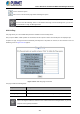
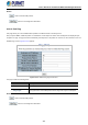
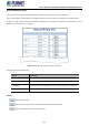
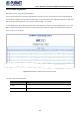


Table Of Contents
- 1. INTRODUCTION
- 2. INSTALLATION
- 3. SWITCH MANAGEMENT
- 4. WEB CONFIGURATION
- 4.1 Main Web Page
- 4.2 System
- 4.2.1 Management
- 4.2.1.1 System Information
- 4.2.1.2 IP Configuration
- 4.2.1.3 IP Status
- 4.2.1.4 ARP
- 4.2.1.5 Users Configuration
- 4.2.1.6 Privilege Levels
- 4.2.1.7 NTP Configuration
- 4.2.1.8 Time Configuration
- 4.2.1.9 Time Configuration
- 4.2.1.10 UPnP
- 4.2.1.11 CPU Load
- 4.2.1.12 System Log
- 4.2.1.13 Detailed Log
- 4.2.1.14 Remote Syslog
- 4.2.1.15 SMTP Configuration
- 4.2.2 SNMP
- 4.2.3 RMON
- 4.2.4 DHCP Relay
- 4.2.5 DHCP server
- 4.2.6 Remote Management
- 4.2.1 Management
- 4.3 Switching
- 4.3.1 Port Management
- 4.3.2 Link Aggregation
- 4.3.3 VLANs
- 4.3.4 VLAN Translation
- 4.3.5 VLAN Translation Mappings
- 4.3.6 Private VLANs
- 4.3.7 VCL
- 4.3.8 GVRP
- 4.3.9 MRP
- 4.3.10 Spanning Tree
- 4.3.11 IGMP Snooping
- 4.3.12 MLD Snooping
- 4.3.13 MVR (Multicast VLAN Registration)
- 4.3.14 LLDP
- 4.3.15 MAC Address Table
- 4.3.16 Loop Protection
- 4.3.17 UDLD
- 4.3.18 Link OAM
- 4.3.19 CFM
- 4.3.20 sFlow
- 4.4 Routing
- 4.5 QoS
- 4.6 Security
- 4.7 POE
- 4.8 Ring
- 4.9 ONVIF
- 4.10 Maintenance
- 5. SWITCH OPERATION
- 6. TROUBLESHOOTING
- APPENDIX A: Networking Connection
- APPENDIX B : GLOSSARY

User’s Manual of GS-6320 and MGS-6320 Managed Switches
460
APPENDIX A: Networking Connection
A.1 Switch's Data RJ45 Pin Assignments - 1000Mbps, 1000BASE-T
PIN NO MDI MDI-X
1
BI_DA+
BI_DB+
2
BI_DA-
BI_DB-
3
BI_DB+
BI_DA+
4
BI_DC+
BI_DD+
5
BI_DC-
BI_DD-
6
BI_DB-
BI_DA-
7
BI_DD+
BI_DC+
8
BI_DD-
BI_DC-
Implicit implementation of the crossover function within a twisted-pair cable, or at a wiring panel, while not expressly forbidden,
is beyond the scope of this standard.
A.2 10/100Mbps, 10/100BASE-TX
When connecting your Switch to another Fast Ethernet switch, a bridge or a hub, a straight or crossover cable is necessary.
Each port of the Switch supports auto-MDI/MDI-X detection. That means you can directly connect the Switch to any Ethernet
devices without making a crossover cable. The following table and diagram show the standard RJ45 receptacle/ connector and
their pin assignments:
RJ45 Connector pin assignment
PIN NO
MDI
Media Dependent Interface
MDI-X
Media Dependent Interface-Cross
1
Tx + (transmit) Rx + (receive)
2
Tx - (transmit) Rx - (receive)
3
Rx + (receive) Tx + (transmit)
4, 5
Not used
6
Rx - (receive)
Tx - (transmit)
7, 8
Not used