
User's Manual
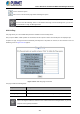
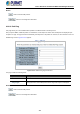
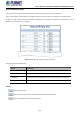
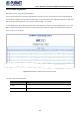

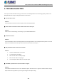


Table Of Contents
- 1. INTRODUCTION
- 2. INSTALLATION
- 3. SWITCH MANAGEMENT
- 4. WEB CONFIGURATION
- 4.1 Main Web Page
- 4.2 System
- 4.2.1 Management
- 4.2.1.1 System Information
- 4.2.1.2 IP Configuration
- 4.2.1.3 IP Status
- 4.2.1.4 ARP
- 4.2.1.5 Users Configuration
- 4.2.1.6 Privilege Levels
- 4.2.1.7 NTP Configuration
- 4.2.1.8 Time Configuration
- 4.2.1.9 Time Configuration
- 4.2.1.10 UPnP
- 4.2.1.11 CPU Load
- 4.2.1.12 System Log
- 4.2.1.13 Detailed Log
- 4.2.1.14 Remote Syslog
- 4.2.1.15 SMTP Configuration
- 4.2.2 SNMP
- 4.2.3 RMON
- 4.2.4 DHCP Relay
- 4.2.5 DHCP server
- 4.2.6 Remote Management
- 4.2.1 Management
- 4.3 Switching
- 4.3.1 Port Management
- 4.3.2 Link Aggregation
- 4.3.3 VLANs
- 4.3.4 VLAN Translation
- 4.3.5 VLAN Translation Mappings
- 4.3.6 Private VLANs
- 4.3.7 VCL
- 4.3.8 GVRP
- 4.3.9 MRP
- 4.3.10 Spanning Tree
- 4.3.11 IGMP Snooping
- 4.3.12 MLD Snooping
- 4.3.13 MVR (Multicast VLAN Registration)
- 4.3.14 LLDP
- 4.3.15 MAC Address Table
- 4.3.16 Loop Protection
- 4.3.17 UDLD
- 4.3.18 Link OAM
- 4.3.19 CFM
- 4.3.20 sFlow
- 4.4 Routing
- 4.5 QoS
- 4.6 Security
- 4.7 POE
- 4.8 Ring
- 4.9 ONVIF
- 4.10 Maintenance
- 5. SWITCH OPERATION
- 6. TROUBLESHOOTING
- APPENDIX A: Networking Connection
- APPENDIX B : GLOSSARY

User’s Manual of GS-6320 and MGS-6320 Managed Switches
451
Buttons
: Click to reboot the system.
: Click to return to the Port State page without rebooting the system.
You can also check the SYS LED
on the front panel to identify whether the System is loaded completely or
not. If the SYS LED is blinking, then it is in the firmware load stage; if the SYS LED light is on, you can use
the Web browser to login the Managed Switch.
4.10.10 Ping
This page allows you to issue ICMP PING packets to troubleshoot IP connectivity issues.
After you press “Start”, 5 ICMP packets are transmitted, and the sequence number and roundtrip time are displayed upon
reception of a reply. The page refreshes automatically until responses to all packets are received, or until a timeout occurs. The
ICMP Ping screen in Figure 4-10-10 appears.
Figure 4-10-10: ICMP Ping Page Screenshot
The page includes the following fields:
Object Description
• IP Address
The destination IP Address.
• Ping Length
The payload size of the ICMP packet. Values range from 2 bytes to 1452 bytes.
Be sure the target IP Address is within the same network subnet of the Managed Switch, or you had
setup the correct gateway IP address.