
User's Manual
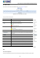
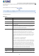
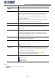
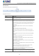

Table Of Contents
- 1. INTRODUCTION
- 2. INSTALLATION
- 3. SWITCH MANAGEMENT
- 4. WEB CONFIGURATION
- 4.1 Main Web Page
- 4.2 System
- 4.2.1 Management
- 4.2.1.1 System Information
- 4.2.1.2 IP Configuration
- 4.2.1.3 IP Status
- 4.2.1.4 ARP
- 4.2.1.5 Users Configuration
- 4.2.1.6 Privilege Levels
- 4.2.1.7 NTP Configuration
- 4.2.1.8 Time Configuration
- 4.2.1.9 Time Configuration
- 4.2.1.10 UPnP
- 4.2.1.11 CPU Load
- 4.2.1.12 System Log
- 4.2.1.13 Detailed Log
- 4.2.1.14 Remote Syslog
- 4.2.1.15 SMTP Configuration
- 4.2.2 SNMP
- 4.2.3 RMON
- 4.2.4 DHCP Relay
- 4.2.5 DHCP server
- 4.2.6 Remote Management
- 4.2.1 Management
- 4.3 Switching
- 4.3.1 Port Management
- 4.3.2 Link Aggregation
- 4.3.3 VLANs
- 4.3.4 VLAN Translation
- 4.3.5 VLAN Translation Mappings
- 4.3.6 Private VLANs
- 4.3.7 VCL
- 4.3.8 GVRP
- 4.3.9 MRP
- 4.3.10 Spanning Tree
- 4.3.11 IGMP Snooping
- 4.3.12 MLD Snooping
- 4.3.13 MVR (Multicast VLAN Registration)
- 4.3.14 LLDP
- 4.3.15 MAC Address Table
- 4.3.16 Loop Protection
- 4.3.17 UDLD
- 4.3.18 Link OAM
- 4.3.19 CFM
- 4.3.20 sFlow
- 4.4 Routing
- 4.5 QoS
- 4.6 Security
- 4.7 POE
- 4.8 Ring
- 4.9 ONVIF
- 4.10 Maintenance
- 5. SWITCH OPERATION
- 6. TROUBLESHOOTING
- APPENDIX A: Networking Connection
- APPENDIX B : GLOSSARY

User’s Manual of GS-6320 and MGS-6320 Managed Switches
435
VLAN-based ETH SNC in Ethernet transport networks. Automatic Protection Switching is defined by the ITU
G.8031 standard.
This page allows the user to create and configure an APS Instance.
The displayed settings are:
APS Protocol:
Object Description
• APS #
The ID of the APS. Maximum number of creatable APS instances is 10 . Click on
link to get to APS instance page, you can reset counters and issue commands.
• Port
The Port this flow is attached to.
• SF Trigger
Selects whether Signal Fail (SF) comes from the link state of a given Port, or
from a Down-MEP.
• SF MEP
The Domain::Service::MEPID refers to a MEP instance which shall represent the
Working flow. Only used when SF Trigger is MEP. The selected MEP instance
does not need to exist when this APS is configured.
• Mode
1:1 This will create a 1:1 APS.
In the linear 1:1 protection switching architecture, the protection transport entity
is dedicated to the working transport entity. However, the normal traffic is
transported either on the working transport entity or on the protection transport
entity using a selector bridge at the source of the protected domain. The selector
at the sink of the protected domain selects the entity which carries the normal
traffic.
1+1 Uni This will create a 1+1 Unidirectional APS.
1+1 Bi This will create a 1+1 Bidirectional APS.
In the linear 1+1 protection switching architecture, a protection transport entity is
dedicated to each working transport entity. The normal traffic is copied and fed to
both working and protection transport entities with a permanent bridge at the
source of the protected domain. The traffic on working and protection transport
entities is transmitted simultaneously to the sink of the protected domain, where
a selection between the working and protection transport entities is made based
on some predetermined criteria, such as server defect indication.
• Level
MD/MEG Level (0-7).
• VLAN
The VLAN ID used in the L-APS PDUs. 0 means untagged.
• PCP
PCP (priority) (default 7). The PCP value used in the VLAN tag unless the L-APS