
User's Manual
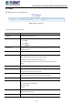
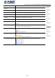
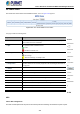
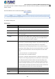
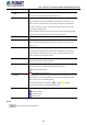
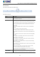
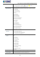

Table Of Contents
- 1. INTRODUCTION
- 2. INSTALLATION
- 3. SWITCH MANAGEMENT
- 4. WEB CONFIGURATION
- 4.1 Main Web Page
- 4.2 System
- 4.2.1 Management
- 4.2.1.1 System Information
- 4.2.1.2 IP Configuration
- 4.2.1.3 IP Status
- 4.2.1.4 ARP
- 4.2.1.5 Users Configuration
- 4.2.1.6 Privilege Levels
- 4.2.1.7 NTP Configuration
- 4.2.1.8 Time Configuration
- 4.2.1.9 Time Configuration
- 4.2.1.10 UPnP
- 4.2.1.11 CPU Load
- 4.2.1.12 System Log
- 4.2.1.13 Detailed Log
- 4.2.1.14 Remote Syslog
- 4.2.1.15 SMTP Configuration
- 4.2.2 SNMP
- 4.2.3 RMON
- 4.2.4 DHCP Relay
- 4.2.5 DHCP server
- 4.2.6 Remote Management
- 4.2.1 Management
- 4.3 Switching
- 4.3.1 Port Management
- 4.3.2 Link Aggregation
- 4.3.3 VLANs
- 4.3.4 VLAN Translation
- 4.3.5 VLAN Translation Mappings
- 4.3.6 Private VLANs
- 4.3.7 VCL
- 4.3.8 GVRP
- 4.3.9 MRP
- 4.3.10 Spanning Tree
- 4.3.11 IGMP Snooping
- 4.3.12 MLD Snooping
- 4.3.13 MVR (Multicast VLAN Registration)
- 4.3.14 LLDP
- 4.3.15 MAC Address Table
- 4.3.16 Loop Protection
- 4.3.17 UDLD
- 4.3.18 Link OAM
- 4.3.19 CFM
- 4.3.20 sFlow
- 4.4 Routing
- 4.5 QoS
- 4.6 Security
- 4.7 POE
- 4.8 Ring
- 4.9 ONVIF
- 4.10 Maintenance
- 5. SWITCH OPERATION
- 6. TROUBLESHOOTING
- APPENDIX A: Networking Connection
- APPENDIX B : GLOSSARY

User’s Manual of GS-6320 and MGS-6320 Managed Switches
432
4.8.2 ERPS
The ERPS instances are configured here.
Figure : ERPS configuration
The page includes the following fields:
Object Description
• ERPS #
The ID of ERPS. Valid range 1 - 64
• RPL Mode
Ring Protection Link mode. Possible values:
None:
Owner:
Neighbor:
• RPL Port
Indicates whether it is port0 or port1 that is the Ring Protection Link. Not used if
RPL Mode is None.
• Ver
ERPS protocol version. v1 and v2 are supported
• Type
Type of ring. Possible values:
Major: ERPS major ring (G.8001-2016, clause 3.2.39)
Sub: ERPS sub-ring (G.8001-2016, clause 3.2.66)
InterSub: ERPS sub-ring on an interconnection node (G.8001-2016, clause
3.2.66)
• VC
Controls whether to use a Virtual Channel with a sub-ring
• Interconnect Instance
For a sub-ring on an interconnection node, this must reference the instance ID of
the ring to which this sub-ring is connected.
• Interconnect Prop
Controls whether the ring referenced by Interconnect Instance shall propagate
R-APS flush PDUs whenever this sub-ring's topology changes.
• Port0/Port1 Interface
Interface index of ring protection Port0/Port1.
• Port0/Port1 SF
Selects whether Signal Fail (SF) comes from the link state of a given interface, or
from a Down-MEP. Possible values:
MEP: Down-MEP
Link: Link
• Ring Id
The Ring ID is used - along with the control VLAN - to identify R-APS PDUs as
belonging to a particular ring.
• Node Id
The Node ID is used inside the R-APS specific PDU to uniquely identify this node