
User's Manual
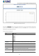

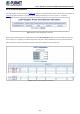

Table Of Contents
- 1. INTRODUCTION
- 2. INSTALLATION
- 3. SWITCH MANAGEMENT
- 4. WEB CONFIGURATION
- 4.1 Main Web Page
- 4.2 System
- 4.2.1 Management
- 4.2.1.1 System Information
- 4.2.1.2 IP Configuration
- 4.2.1.3 IP Status
- 4.2.1.4 ARP
- 4.2.1.5 Users Configuration
- 4.2.1.6 Privilege Levels
- 4.2.1.7 NTP Configuration
- 4.2.1.8 Time Configuration
- 4.2.1.9 Time Configuration
- 4.2.1.10 UPnP
- 4.2.1.11 CPU Load
- 4.2.1.12 System Log
- 4.2.1.13 Detailed Log
- 4.2.1.14 Remote Syslog
- 4.2.1.15 SMTP Configuration
- 4.2.2 SNMP
- 4.2.3 RMON
- 4.2.4 DHCP Relay
- 4.2.5 DHCP server
- 4.2.6 Remote Management
- 4.2.1 Management
- 4.3 Switching
- 4.3.1 Port Management
- 4.3.2 Link Aggregation
- 4.3.3 VLANs
- 4.3.4 VLAN Translation
- 4.3.5 VLAN Translation Mappings
- 4.3.6 Private VLANs
- 4.3.7 VCL
- 4.3.8 GVRP
- 4.3.9 MRP
- 4.3.10 Spanning Tree
- 4.3.11 IGMP Snooping
- 4.3.12 MLD Snooping
- 4.3.13 MVR (Multicast VLAN Registration)
- 4.3.14 LLDP
- 4.3.15 MAC Address Table
- 4.3.16 Loop Protection
- 4.3.17 UDLD
- 4.3.18 Link OAM
- 4.3.19 CFM
- 4.3.20 sFlow
- 4.4 Routing
- 4.5 QoS
- 4.6 Security
- 4.7 POE
- 4.8 Ring
- 4.9 ONVIF
- 4.10 Maintenance
- 5. SWITCH OPERATION
- 6. TROUBLESHOOTING
- APPENDIX A: Networking Connection
- APPENDIX B : GLOSSARY

User’s Manual of GS-6320 and MGS-6320 Managed Switches
423
4.7.8 PoE Alive Check Configuration
The GS-6320 and MGS-6320 Switch can be configured to monitor connected PD’s status in real-time via ping action. Once the
PD stops working and without response, GS-6320 and MGS-6320 Switch is going to restart PoE port port power, and bring the
PD back to work. It will greatly enhance the reliability and reduces administrator management burden.
This page provides you how to configure PD Alive Check.The screen in Figure 4-7-8 appears.
Figure 4-7-8: PD Alive Check Configuration Screenshot