
User's Manual

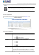
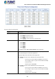
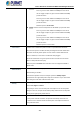
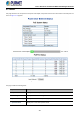
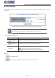
Table Of Contents
- 1. INTRODUCTION
- 2. INSTALLATION
- 3. SWITCH MANAGEMENT
- 4. WEB CONFIGURATION
- 4.1 Main Web Page
- 4.2 System
- 4.2.1 Management
- 4.2.1.1 System Information
- 4.2.1.2 IP Configuration
- 4.2.1.3 IP Status
- 4.2.1.4 ARP
- 4.2.1.5 Users Configuration
- 4.2.1.6 Privilege Levels
- 4.2.1.7 NTP Configuration
- 4.2.1.8 Time Configuration
- 4.2.1.9 Time Configuration
- 4.2.1.10 UPnP
- 4.2.1.11 CPU Load
- 4.2.1.12 System Log
- 4.2.1.13 Detailed Log
- 4.2.1.14 Remote Syslog
- 4.2.1.15 SMTP Configuration
- 4.2.2 SNMP
- 4.2.3 RMON
- 4.2.4 DHCP Relay
- 4.2.5 DHCP server
- 4.2.6 Remote Management
- 4.2.1 Management
- 4.3 Switching
- 4.3.1 Port Management
- 4.3.2 Link Aggregation
- 4.3.3 VLANs
- 4.3.4 VLAN Translation
- 4.3.5 VLAN Translation Mappings
- 4.3.6 Private VLANs
- 4.3.7 VCL
- 4.3.8 GVRP
- 4.3.9 MRP
- 4.3.10 Spanning Tree
- 4.3.11 IGMP Snooping
- 4.3.12 MLD Snooping
- 4.3.13 MVR (Multicast VLAN Registration)
- 4.3.14 LLDP
- 4.3.15 MAC Address Table
- 4.3.16 Loop Protection
- 4.3.17 UDLD
- 4.3.18 Link OAM
- 4.3.19 CFM
- 4.3.20 sFlow
- 4.4 Routing
- 4.5 QoS
- 4.6 Security
- 4.7 POE
- 4.8 Ring
- 4.9 ONVIF
- 4.10 Maintenance
- 5. SWITCH OPERATION
- 6. TROUBLESHOOTING
- APPENDIX A: Networking Connection
- APPENDIX B : GLOSSARY

User’s Manual of GS-6320 and MGS-6320 Managed Switches
415
802.3bt: Set inline mode to IEEE 802.3bt PoE++ Type-4 or Type-3 PSE.
Pins 1-2 (pair #2 in both T568A and T568B) form one side of
the DC supply and pins 3-6 (pair #3 in both T568A and T568B)
provide the return.
Pins 4-5 (pair #1 in both T568A and T568B) form one side of
the DC supply and pins 7-8 (pair #4 in both T568A and T568B)
provide the return.
Maximum power is 90~60 watts.
UPOE: Set inline mode to PoH (Power over HD-BASE-T) 4-pair PoE+ PSE
Pins 1-2 (pair #2 in both T568A and T568B) form one side of
the DC supply and pins 3-6 (pair #3 in both T568A and T568B)
provide the return.
Pins 4-5 (pair #1 in both T568A and T568B) form one side of
the DC supply and pins 7-8 (pair #4 in both T568A and T568B)
provide the return
Maximum power is 72-60.0 watts
• Force Power
It allows user to enable force power function in a specified PoE Inline mode.
Once the force power is enabled, the PoE port will ignore the PoE classification
behaviors and directly deliver power over UTP cable no matter what Ethernet
device is attached, or even there is no Ethernet cable plugged.
Please be careful when using force power function and make sure the remote
device is PoE powered device (PD).
Maximum power is 60 watts when PoE Inline mode is configured to 8023bt or
UPOE mode.
• PoE Extension
For user to enable or disable per port PoE Extension function.
Default setting is "Disable".
In the Extend operation mode, the PoE port operates at 10Mbps duplex
operation but can support PoE power output over a distance of up to 160 meters
overcoming the 100m limit on Ethernet UTP cable.
• Priority
The Priority represents PoE ports priority. There are three levels of power priority
named Low, High and Critical.
The priority is used in case the total power consumption is over the total power
budget. In this case, the port with the lowest priority will be turned off, and power
for the port of higher priority will be offered.
• Power Allocation
The Powe Allocation column shows per port maximum value of PoE power.
Once power overload is detected, the port will automatically shut down and
continue to be in detection mode until Pad’s power consumption is lower than
the power limit value.