
User's Manual

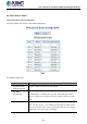
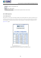

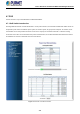
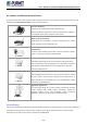
Table Of Contents
- 1. INTRODUCTION
- 2. INSTALLATION
- 3. SWITCH MANAGEMENT
- 4. WEB CONFIGURATION
- 4.1 Main Web Page
- 4.2 System
- 4.2.1 Management
- 4.2.1.1 System Information
- 4.2.1.2 IP Configuration
- 4.2.1.3 IP Status
- 4.2.1.4 ARP
- 4.2.1.5 Users Configuration
- 4.2.1.6 Privilege Levels
- 4.2.1.7 NTP Configuration
- 4.2.1.8 Time Configuration
- 4.2.1.9 Time Configuration
- 4.2.1.10 UPnP
- 4.2.1.11 CPU Load
- 4.2.1.12 System Log
- 4.2.1.13 Detailed Log
- 4.2.1.14 Remote Syslog
- 4.2.1.15 SMTP Configuration
- 4.2.2 SNMP
- 4.2.3 RMON
- 4.2.4 DHCP Relay
- 4.2.5 DHCP server
- 4.2.6 Remote Management
- 4.2.1 Management
- 4.3 Switching
- 4.3.1 Port Management
- 4.3.2 Link Aggregation
- 4.3.3 VLANs
- 4.3.4 VLAN Translation
- 4.3.5 VLAN Translation Mappings
- 4.3.6 Private VLANs
- 4.3.7 VCL
- 4.3.8 GVRP
- 4.3.9 MRP
- 4.3.10 Spanning Tree
- 4.3.11 IGMP Snooping
- 4.3.12 MLD Snooping
- 4.3.13 MVR (Multicast VLAN Registration)
- 4.3.14 LLDP
- 4.3.15 MAC Address Table
- 4.3.16 Loop Protection
- 4.3.17 UDLD
- 4.3.18 Link OAM
- 4.3.19 CFM
- 4.3.20 sFlow
- 4.4 Routing
- 4.5 QoS
- 4.6 Security
- 4.7 POE
- 4.8 Ring
- 4.9 ONVIF
- 4.10 Maintenance
- 5. SWITCH OPERATION
- 6. TROUBLESHOOTING
- APPENDIX A: Networking Connection
- APPENDIX B : GLOSSARY

User’s Manual of GS-6320 and MGS-6320 Managed Switches
410
The PD is classified based on power. The classification of the PD is the maximum power that the PD will draw across all input
voltages and operational modes.
A PD will return to Class 0 to 8 in accordance with the maximum power draw as specified by Table 4-7-2-1.
Class
Usage
Range of maximum power used by the PD
Class Description
0
Default
0.44 to 12.95 watts
Classification unimplement
1
Optional 0.44 to 3.84 watts
Very low power
2
Optional
3.84 to 6.49 watts
Low power
3
Optional
6.49 to 12.95 watts (or to 15.4 watts)
Mid power
4
Valid for Type 2 (802.3at)
devices,
not allowed for 802.3af devices
12.95 to 25.5 watts
High power
5
Valid for Type 3 (802.3bt)
devices
40 watts
6
51 watts (4-pair)
7
Valid for Type 4 (802.3bt)
devices
62 watts (4-pair)
8
71.3 watts (4-pair)
Table 4-7-2-1 Device Class.
4.7.3 PoE System Configuration
Under some conditions, the total output power required by PDs can exceed the maximum available power provided by the PSU.
The system may come with a PSU capable of supplying less power than the total potential power consumption of all the PoE
ports in the system. In order to maintain the activity of the majority of ports, PoE power management is implemented.
The PSU input power consumption is monitored by measuring voltage and current .The input power consumption is equal to the
system’s aggregated power consumption .The PoE power management concept allows all ports to be active and activates
additional ports, as long as the aggregated power of the system is lower than the power level at which additional PDs cannot be
connected .When this value is exceeded, ports will be deactivated, according to user-defined priorities. The power budget is
managed according to the following user-definable parameters: maximum available power, ports priority, maximum
allowable power per port.
Reserved Power determined by
There are two modes for configuring how the ports/PDs may reserve power and when to shut down ports.
Classification mode
In this mode each port automatically determines how much power to reserve according to the class the connected PD
belongs to, and reserves the power accordingly. Four different port classes exist and one for 4, 7, 15.4 and 30.8 watts.
Allocation mode
In this mode the user allocates the amount of power that each port may reserve. The allocated/reserved power for each
port/PD is specified in the Maximum Power fields. The ports are shut down when total reserved powered exceeds the