
User's Manual
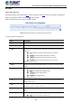
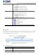


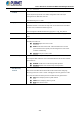
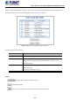
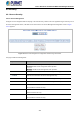
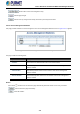
Table Of Contents
- 1. INTRODUCTION
- 2. INSTALLATION
- 3. SWITCH MANAGEMENT
- 4. WEB CONFIGURATION
- 4.1 Main Web Page
- 4.2 System
- 4.2.1 Management
- 4.2.1.1 System Information
- 4.2.1.2 IP Configuration
- 4.2.1.3 IP Status
- 4.2.1.4 ARP
- 4.2.1.5 Users Configuration
- 4.2.1.6 Privilege Levels
- 4.2.1.7 NTP Configuration
- 4.2.1.8 Time Configuration
- 4.2.1.9 Time Configuration
- 4.2.1.10 UPnP
- 4.2.1.11 CPU Load
- 4.2.1.12 System Log
- 4.2.1.13 Detailed Log
- 4.2.1.14 Remote Syslog
- 4.2.1.15 SMTP Configuration
- 4.2.2 SNMP
- 4.2.3 RMON
- 4.2.4 DHCP Relay
- 4.2.5 DHCP server
- 4.2.6 Remote Management
- 4.2.1 Management
- 4.3 Switching
- 4.3.1 Port Management
- 4.3.2 Link Aggregation
- 4.3.3 VLANs
- 4.3.4 VLAN Translation
- 4.3.5 VLAN Translation Mappings
- 4.3.6 Private VLANs
- 4.3.7 VCL
- 4.3.8 GVRP
- 4.3.9 MRP
- 4.3.10 Spanning Tree
- 4.3.11 IGMP Snooping
- 4.3.12 MLD Snooping
- 4.3.13 MVR (Multicast VLAN Registration)
- 4.3.14 LLDP
- 4.3.15 MAC Address Table
- 4.3.16 Loop Protection
- 4.3.17 UDLD
- 4.3.18 Link OAM
- 4.3.19 CFM
- 4.3.20 sFlow
- 4.4 Routing
- 4.5 QoS
- 4.6 Security
- 4.7 POE
- 4.8 Ring
- 4.9 ONVIF
- 4.10 Maintenance
- 5. SWITCH OPERATION
- 6. TROUBLESHOOTING
- APPENDIX A: Networking Connection
- APPENDIX B : GLOSSARY

User’s Manual of GS-6320 and MGS-6320 Managed Switches
332
■ Ethernet: Only Ethernet frames (with Ether Type 0x600-0xFFFF) are
allowed.
■ LLC: Only (LLC) frames are allowed.
■ SNAP: Only (SNAP) frames are allowed.
■ IPv4: The QCE will match only IPV4 frames.
■ IPv6: The QCE will match only IPV6 frames.
• Action
Indicates the classification action taken on ingress frame if parameters
configured are matched with the frame's content.
There are three action fields: Class, DPL and DSCP.
■ Class: Classified QoS class.
■ DPL: Classified Drop Precedence Level.
■ DSCP: Classified DSCP value.
• Modification Buttons
You can modify each QCE in the table using the following buttons:
: Inserts a new QCE before the current row.
: Edits the QCE.
: Moves the QCE up the list.
: Moves the QCE down the list.
: Deletes the QCE.
: The lowest plus sign adds a new entry at the bottom of the list of QCL.
4.5.5.2 QCL Status
This page shows the QCL status by different QCL users. Each row describes the QCE that is defined. It is a conflict if a specific
QCE is not applied to the hardware due to hardware limitations. The maximum number of QCEs is 256 on each switch. The
QoS Control List Status screen in Figure 4-5-5-2 appears.
Figure 4-5-5-2: QoS Control List Status Page Screenshot
The page includes the following fields:
Object Description
• User
Indicates the QCL user.
• QCE#
Indicates the index of QCE.