
User's Manual
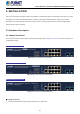
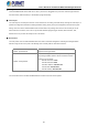


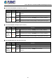
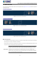
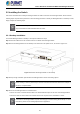
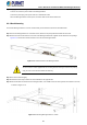
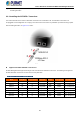
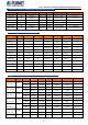
Table Of Contents
- 1. INTRODUCTION
- 2. INSTALLATION
- 3. SWITCH MANAGEMENT
- 4. WEB CONFIGURATION
- 4.1 Main Web Page
- 4.2 System
- 4.2.1 Management
- 4.2.1.1 System Information
- 4.2.1.2 IP Configuration
- 4.2.1.3 IP Status
- 4.2.1.4 ARP
- 4.2.1.5 Users Configuration
- 4.2.1.6 Privilege Levels
- 4.2.1.7 NTP Configuration
- 4.2.1.8 Time Configuration
- 4.2.1.9 Time Configuration
- 4.2.1.10 UPnP
- 4.2.1.11 CPU Load
- 4.2.1.12 System Log
- 4.2.1.13 Detailed Log
- 4.2.1.14 Remote Syslog
- 4.2.1.15 SMTP Configuration
- 4.2.2 SNMP
- 4.2.3 RMON
- 4.2.4 DHCP Relay
- 4.2.5 DHCP server
- 4.2.6 Remote Management
- 4.2.1 Management
- 4.3 Switching
- 4.3.1 Port Management
- 4.3.2 Link Aggregation
- 4.3.3 VLANs
- 4.3.4 VLAN Translation
- 4.3.5 VLAN Translation Mappings
- 4.3.6 Private VLANs
- 4.3.7 VCL
- 4.3.8 GVRP
- 4.3.9 MRP
- 4.3.10 Spanning Tree
- 4.3.11 IGMP Snooping
- 4.3.12 MLD Snooping
- 4.3.13 MVR (Multicast VLAN Registration)
- 4.3.14 LLDP
- 4.3.15 MAC Address Table
- 4.3.16 Loop Protection
- 4.3.17 UDLD
- 4.3.18 Link OAM
- 4.3.19 CFM
- 4.3.20 sFlow
- 4.4 Routing
- 4.5 QoS
- 4.6 Security
- 4.7 POE
- 4.8 Ring
- 4.9 ONVIF
- 4.10 Maintenance
- 5. SWITCH OPERATION
- 6. TROUBLESHOOTING
- APPENDIX A: Networking Connection
- APPENDIX B : GLOSSARY

User’s Manual of GS-6320 and MGS-6320 Managed Switches
33
2.1.2 LED Indications
The front panel LEDs indicate instant statuses of power and system, ring, port links and data activity; they help monitor and
troubleshoot when needed. Figures 2-1-2-1 and 2-1-2-3 show the LED indications of the Managed Switches.
GS-6320-8P2X LED Indication
Figure 2-1-2-1: Front Panel of GS-6320-8P2X
MGS-6320-8HP2X LED Indication
Figure 2-1-2-2: Front Panel of MGS-6320-8HP2X
MGS-6320-8T2X LED Indication
Figure 2-1-2-3: Front Panel of MGS-6320-8T2X
System (GS-6320-8P2X / MGS-6320-8HP2X / MGS-6320-8T2X )
LED Color Function
R.O.
Green
Lights to indicate that Switch has enabled Ring Owner.
Ring Green
Lights to indicate the ERPS Ring has been created successfully
Off to indicate the Ring function is not working
SYS
Green
Lights to indicate the system is working.
PWR
Green
Lights to indicate that the Switch has power.