
User's Manual
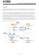
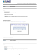

Table Of Contents
- 1. INTRODUCTION
- 2. INSTALLATION
- 3. SWITCH MANAGEMENT
- 4. WEB CONFIGURATION
- 4.1 Main Web Page
- 4.2 System
- 4.2.1 Management
- 4.2.1.1 System Information
- 4.2.1.2 IP Configuration
- 4.2.1.3 IP Status
- 4.2.1.4 ARP
- 4.2.1.5 Users Configuration
- 4.2.1.6 Privilege Levels
- 4.2.1.7 NTP Configuration
- 4.2.1.8 Time Configuration
- 4.2.1.9 Time Configuration
- 4.2.1.10 UPnP
- 4.2.1.11 CPU Load
- 4.2.1.12 System Log
- 4.2.1.13 Detailed Log
- 4.2.1.14 Remote Syslog
- 4.2.1.15 SMTP Configuration
- 4.2.2 SNMP
- 4.2.3 RMON
- 4.2.4 DHCP Relay
- 4.2.5 DHCP server
- 4.2.6 Remote Management
- 4.2.1 Management
- 4.3 Switching
- 4.3.1 Port Management
- 4.3.2 Link Aggregation
- 4.3.3 VLANs
- 4.3.4 VLAN Translation
- 4.3.5 VLAN Translation Mappings
- 4.3.6 Private VLANs
- 4.3.7 VCL
- 4.3.8 GVRP
- 4.3.9 MRP
- 4.3.10 Spanning Tree
- 4.3.11 IGMP Snooping
- 4.3.12 MLD Snooping
- 4.3.13 MVR (Multicast VLAN Registration)
- 4.3.14 LLDP
- 4.3.15 MAC Address Table
- 4.3.16 Loop Protection
- 4.3.17 UDLD
- 4.3.18 Link OAM
- 4.3.19 CFM
- 4.3.20 sFlow
- 4.4 Routing
- 4.5 QoS
- 4.6 Security
- 4.7 POE
- 4.8 Ring
- 4.9 ONVIF
- 4.10 Maintenance
- 5. SWITCH OPERATION
- 6. TROUBLESHOOTING
- APPENDIX A: Networking Connection
- APPENDIX B : GLOSSARY

User’s Manual of GS-6320 and MGS-6320 Managed Switches
257
4.4.5.2 Network Area
OSPF protocol broadcast messages (i.e., Link State Advertisements) are restricted by area to limit their impact on network
performance. Before assigning an Area ID to a specific OSPF interface, you must first specify the Area ID in this table. Each
entry in this table identifies a logical group of OSPF routers that actively exchange Link State Advertisements (LSAs) to
ensure that they share an identical view of the network topology. You can configure the area as a normal one which can send
and receive external Link State Advertisements (LSAs), a stubby area that cannot send or receive external LSAs, or a
not-so-stubby area (NSSA) that can import external route information into its area.
Following is OSPF area configuration table. It is used to specify the OSPF enabled interface(s). When OSPF is enabled on the
specific interface(s), the router can provide the network information to the other OSPF routers via those interfaces. The screen
in Figure 4-4-5-2 appears.
Figure 4-4-5-2: OSPF Network Area Page Screenshot
The page includes the following fields:
Object Description
Network Address IPv4 network address.