
User's Manual
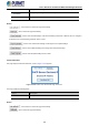
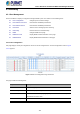
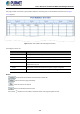
Table Of Contents
- 1. INTRODUCTION
- 2. INSTALLATION
- 3. SWITCH MANAGEMENT
- 4. WEB CONFIGURATION
- 4.1 Main Web Page
- 4.2 System
- 4.2.1 Management
- 4.2.1.1 System Information
- 4.2.1.2 IP Configuration
- 4.2.1.3 IP Status
- 4.2.1.4 ARP
- 4.2.1.5 Users Configuration
- 4.2.1.6 Privilege Levels
- 4.2.1.7 NTP Configuration
- 4.2.1.8 Time Configuration
- 4.2.1.9 Time Configuration
- 4.2.1.10 UPnP
- 4.2.1.11 CPU Load
- 4.2.1.12 System Log
- 4.2.1.13 Detailed Log
- 4.2.1.14 Remote Syslog
- 4.2.1.15 SMTP Configuration
- 4.2.2 SNMP
- 4.2.3 RMON
- 4.2.4 DHCP Relay
- 4.2.5 DHCP server
- 4.2.6 Remote Management
- 4.2.1 Management
- 4.3 Switching
- 4.3.1 Port Management
- 4.3.2 Link Aggregation
- 4.3.3 VLANs
- 4.3.4 VLAN Translation
- 4.3.5 VLAN Translation Mappings
- 4.3.6 Private VLANs
- 4.3.7 VCL
- 4.3.8 GVRP
- 4.3.9 MRP
- 4.3.10 Spanning Tree
- 4.3.11 IGMP Snooping
- 4.3.12 MLD Snooping
- 4.3.13 MVR (Multicast VLAN Registration)
- 4.3.14 LLDP
- 4.3.15 MAC Address Table
- 4.3.16 Loop Protection
- 4.3.17 UDLD
- 4.3.18 Link OAM
- 4.3.19 CFM
- 4.3.20 sFlow
- 4.4 Routing
- 4.5 QoS
- 4.6 Security
- 4.7 POE
- 4.8 Ring
- 4.9 ONVIF
- 4.10 Maintenance
- 5. SWITCH OPERATION
- 6. TROUBLESHOOTING
- APPENDIX A: Networking Connection
- APPENDIX B : GLOSSARY

User’s Manual of GS-6320 and MGS-6320 Managed Switches
107
4.3 Switching
4.3.1 Port Management
Use the Port Menu to display or configure the Managed Switch's ports. This section has the following items:
Port Configuration Configures port connection settings
Port Statistics Overview Lists Ethernet and RMON port statistics
Port Statistics Detail Lists Ethernet and RMON port statistics
Port Mirror Sets the source and target ports for mirroring
Name Map Interface Name to Port Number Map
DDMI Configure DDMI on this page.
DDMI Over View Display DDMI overview information on this page.
DDMI Detailed Display DDMI detailed information on this page.
4.3.1.1 Port Configuration
This page displays current port configurations. Ports can also be configured here. The Port Configuration screen in Figure
4-3-1-1 appears.
Figure 4-3-1-1: Port Configuration Page Screenshot
The page includes the following fields:
Object Description
• Port
This is the logical port number for this row.
• Port Description
Indicates the per port description.
• Link
The current link state is displayed graphically. Green indicates the link is up and
red indicates the link is down.
• Current Link Speed
Provides the current link speed of the port.