User's Manual MC-1610MR MC-1610MR48 16-Slot Managed Media Converter Chassis 1
Trademarks Copyright © PLANET Technology Corp. 2009. Contents subject to revision without prior notice. PLANET is a registered trademark of PLANET Technology Corp. All other trademarks belong to their respective owners. Disclaimer PLANET Technology does not warrant that the hardware will work properly in all environments and applications, and makes no warranty and representation, either implied or expressed, with respect to the quality, performance, merchantability, or fitness for a particular purpose.
TABLE OF CONTENTS 1. INTRODUCTION..............................................................................................................................5 1.1 PACKAGE CONTENTS ......................................................................................................................................5 1.2 HOW TO USE THIS MANUAL .............................................................................................................................5 1.
5.3.4 Password Setting ..................................................................................................................................................51 5.3.5 Firmware Upgrade ................................................................................................................................................52 5.3.6 Factory Default.....................................................................................................................................................
1. INTRODUCTION 1.
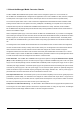
1.3 About the Managed Media Converter Chassis The MC-1610MR / MC-1610MR48 series provide 16-slots and one management system in a 19”-rack chassis, the MC-1610MR / MC-1610MR48 series is designed for the applications such as FTTx installation for ISPs, telecoms, campuses and enterprises. Various types of optic connectors, and fiber-optic wires on the distance basis are provides flexibly.
1.
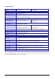
1.5 Specification Model MC-1610MR MC-1610MR48 Hardware Specification Dimension (W x D xH) 440 x 88 x 350mm, 2U Slot 16 open Slot( 15 x 80 x 26mm, W x D x H) 2 power slot s (one fixed, one vacant* ) Weight 7kg Power requirement 100-240V AC, 1A, 50-60Hz DC -48V , 2A, Range: -40V ~ -60V Power Output 5V DC per slot, 2A maximum Power consumption 10 Watts / 34BTU (1 x power sup- 5.3 Watts / 18BTU (1 x power supply, not ply , not include converters) include converters) 46.
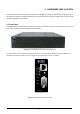
2. HARDWARE INSTALLATION This section describes the functionalities of MC-1610MR / MC-1610MR48 components and guides how to install the device on the desktop or shelf. Basic knowledge of networking is assumed; please read this chapter completely before continuing installs the Managed Media Converter Chassis. 2.1 Front Panel The Managed Media Converter Chassis provides one management module and 16-Slots for optional FST-8 / GST-7 / GST-8 series Fast / Gigabit Ethernet Smart Media converter installation.
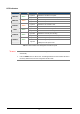
LED Indicators LED Color PWR ON Green PWR FAIL Amber FAN FAIL Amber MGM Green CONSOLE Green LNK/ACT Green LED Status Function Lights On Indicate that the device has power. Lights Off Indicate that the device not receive power. Lights On Indicate that power is inserted and failed to work. Lights Off Indicate that power is inserted and work normal. Lights On Indicate that fan is failed to work. Lights Off Indicate that fan is work normally.
2.2 Rear Panel The MC-1610MR equip with one 100~240V AC power supply unit and MC-1610MR48 equip with one DC -48V power supply unit on its standard package, both MC-1610MR and MC-1610MR48 provide one spare power supply unit slot for option redundant power supply installation. A redundant power supply is also provided to enhance the reliability with options of either 100~240V AC power supply unit or DC -48V power supply unit.
2.3 Managed Media Converter Chassis Installation The chapter describes how to install optional FST-8 / GST-7 / GST-8 series Fast / Gigabit Ethernet Smart Media converter into your Managed Media Converter Chassis, please read the following topics and perform the procedures in the order being presented. To install your Managed Media Converter Chassis on a desktop or shelf, simply complete the following steps. 2.3.
2.3.2 Rack Mounting To install the Managed Media Converter Chassis in a 19-inch standard rack, follow the instructions described below. Step 1: Place your Managed Media Converter Chassis on a hard flat surface, with the front panel positioned towards your front side. Step 2: Attach a rack-mount bracket to each side of the Managed Media Converter Chassis with supplied screws attached to the package. Figure 2-5 shows how to attach brackets to one side of the Managed Media Converter Chassis.
2.3.3 Slide Media Converter board into MC-1610MR /MC-1610MR48 Chassis Installation Step 1: unscrew and pull out the FST-80x / GST-70x / GST-80x Media Converter board. Step 2: Remove a blank faceplate from an empty expansion slot on the front of the chassis. The FST-80x / GST-70x / GST-80x Media Converter board can be installed in any expansion slot.
Step 4: Secure the FST-80x / GST-70x / GST-80x Media Converter board to the chassis by tightening the thumbscrew. 2.3.4 Centralize management Media Converter application Affording the current network grows and expanding, the PLANET MC-1610MR / MC-1610MR48 series provide advanced Media conversion technology to fill this kind of demands.
3. MANAGED MEDIA CONVERTER CHASSIS MANAGEMENT This chapter describes how to manage the Managed Media Converter Chassis. Topics include: - Overview - Management methods - Assigning an IP address to the Managed Media Converter Chassis - Logging on to the Managed Media Converter Chassis 3.1 Overview The Managed Media Converter Chassis provides user-friendly, command line console interface and remote Web interface.
Figure 3-1 Managed Media Converter Chassis Console Login Screen The factory default login username and password is admin. #Notice: 1. For security reason, please change and memorize the new password after this first setup. 2. Only accept command in lowercase letter under console interface. 3. Please refer to the following Chapter 4 for the details.
3.2.2 Web Management You can manage the Managed Media Converter Chassis remotely by having a remote host with web browser, such as Microsoft Internet Explorer or Netscape Navigator. Using this management method: The Managed Media Converter Chassis must have an Internet Protocol (IP) address accessible for the remote host. For easily list the Managed Media Converter Chassis in your Ethernet environment, the Planet Smart Discovery Utility from user’s manual CD-ROM is an ideal solution.
3. Press “Refresh” button for list current connected devices in the discovery list, the screen is shown as follow. Figure 3-3 Planet Smart Discovery Utility Screen 4. This utility show all necessary information from the devices, such as MAC Address, Device Name, firmware version, Device IP Subnet address, also can assign new password, IP Subnet address and description for the devices. 5. After setup completed, press “Update Device”, “Update Multi” or “Update All” button to take affect.
8. Press “Exit” button to shutdown the planet Smart Discovery Utility. #Notice: Please refer to the following Chapter 5 for the details. 3.3 Assigning an IP Address to the Managed Media Converter Chassis To manage the Managed Media Converter Chassis remotely through the web browser with a Management Station, you can use its default IP address (192.168.0.100) or assign another IP address to the Managed Media Converter Chassis. To set the IP address, please use command. set ip xxx.xxx.xxx.xxx mmm.mmm.mmm.
4. CONSOLE INTERFACE 4.1 CONNECT TO PC RS-232 serial cable Use the bundled RS-232 serial cable and attach the 9-pin female connector to the male connector on the Managed Media Converter Chassis. Plug the other side of this cable to your PC.
4.2 Login in Login is required to access the console interface after the self-test completes successfully. The factory default user name and password is "admin". You may change the password by use “set pass” command. Please always enter the correct user name and password. (See Figure 4-2) Figure 4-2 Managed Media Converter Chassis login screen 4.3 Main Menu screen After login the Managed Media Converter Chassis, the main menu screen shows as below.
4.4 Getting Started 4.4.1 General Guidelines The Managed Media Converter Chassis allows users to configure the device via command line under console interface. Please type “help” or “?” for all available commands in the”MC-1610MR>” prompt. The screen of available commands in Figure 4-4 appears, and the detail description shown in table 4-1.
Factory Default Reset the Managed Media Converter Chassis to factory default mode. Reboot Reboot the Managed Media Converter Chassis. Logout Logout console interface of Managed Media Converter Chassis. Table 4-1 Detail description of Managed Media Converter Chassis available commands #Notice: Only accept command in lowercase letter under console interface. 4.4.2 Show command From the main menu screen (see Figure 4-3), input “show” and press enter. The show command list screen in Figure 4-5 appears.
4.4.2.1 Show system Display the system information of Managed Media Converter Chassis, such as software version, MAC address and IP address. The system information screen in Figure 4-6 appears. Figure 4-6 Show system command screen 4.4.2.2 Show IP Display the current IP address, Subnet mask and Gateway of Managed Media Converter Chassis, the IP subnet address information screen in Figure 4-7 appears. Figure 4-7 Show IP command screen 4.4.2.
4.4.2.4 Show slot [n] Display current per slot status of Managed Media Converter Chassis with FST-8 / GST-7 / GST-8 Media Converter boards, the per slot information screen in Figure 4-9 & 4-10 & 4-11 & 4-12 appears.
Figure 4-11 GST-70x Show slot command [n] screen Figure 4-12 GST-80x Show slot command [n] screen #Notice: Different parameters display on FST-8 / GST-7 / GST-8 Media Converter boards installation.
4.4.2.5 Show redundant [n] Display per redundant group status of Managed Media Converter Chassis, the per redundant group status screen in Figure 4-13 & 4-14 appears.
4.4.3 Set command From the main menu screen (see Figure 4-3), input “set” and press enter. The set command list screen in Figure 4-15 appears. Figure 4-15 Set command list screen This set command list contains four items: Set slot [n]: Please refer to chapter 4.4.3.1. Set redundant [n] disable / enable: Please refer to chapter 4.4.3.2. Set ip xxx.xxx.xxx.xxx.mmm.mmm.mmm.mmm.ggg.ggg.ggg.ggg: Please refer to chapter 4.4.3.3 Set pass [oldpass] [newpass]: Please refer to chapter 4.4.3.
4.4.3.1 Set slot [n] This command allows configuring per slot parameters of Managed Media Converter Chassis, different parameters provide on FST-8 / GST-7 / GST-8 Media Converter boards installation. The correct usage is shown as below: Set slot [n]: n=1-16, to configuring per slot parameters of Managed Media Converter Chassis. The configuring per slot parameters screen in Figure 4-16 appears and the detail description shown in table 4-2 & 4-3 & 4-4.
Item Description Device To enable or disable per GST-80x Converter board. LLCF To enable or disable the LLCF function from GST-80x Converter board. TP AN Mode To set the UTP port runs at Auto-negotiation or Forced Mode. TP Speed* To set the UTP port runs at 1000Mbps,100Mbps or 10Mbps. TP Duplex* To set the UTP port runs at Full duplex or Half duplex mode. TP Flow Control To set the Flow Control of the UTP port to enable or disable.
4.4.3.2 Set redundant [n] disable/enable This command allows disable or enable per redundant group of Managed Media Converter Chassis, the correct usage is shown as below: Set redundant[n]disable/enable: n=1-8, to disable or enable per redundant group of Managed Media Converter Chassis, the screen in Figure 4-17 appears.
4.4.3.3 Set IP xxx,xxx,xxx,xxx,mmm,mmm,mmm,mmm, ggg,ggg,ggg,ggg This command allows assign IP address, subnet mask and gateway of Managed Media Converter Chassis; the correct usage is shown as below: set ip 192.168.0.101 255.255.255.0 192.168.0.254 and press Then the following message appears under console interface: Set ip done Means the IP address was changed successfully, the IP subnet address setting screen in Figure 4-18 appears. Figure 4-18 Set IP command screen 4.4.3.
4.4.4 Factory default This command allows reset the Managed Media Converter Chassis to factory default mode. The factory default screen in Figure 4-20 & 4-21 appears.
4.4.5 Reboot This command allows reboot the Managed Media Converter Chassis, the reboot screen in Figure 4-22 & 4-23 appears. Figure 4-22 Managed Media Converter Chassis reboot screen Figure 4-23 Managed Media Converter Chassis reboot screen 4.4.6 Logout This command provides logout the Managed Media Converter Chassis, the screen in Figure 4-24 appears.
5. WEB MANAGEMENT Before login the Web interface of Managed Media Converter Chassis, please setup the “IP Address” with local serial console port (RS232 port) and use this IP address to configure Managed Media Converter Chassis through the Web interface. Or modify your PC’s IP domain to the same with Managed Media Converter Chassis then use the default IP address (192.168.0.100) to remote configure Managed Media Converter Chassis through the Web interface. 5.
The four major items and it description shown as below: ◆ Module Status: Provide Module Status function of Managed Media Converter Chassis. Explained in section 5.2. ◆ Management: Provide Management function of Managed Media Converter Chassis. Explained in section 5.3. ◆ SNMP: Provide SNMP configuration of Managed Media Converter Chassis. Explained in section 5.4. ◆ Logout: Provide Logout function of Managed Media Converter Chassis. Explained in section 5.5.
5.2 Module Status This section provides Chassis Status, Converter Status, Location Setting and Redundant Backup Setting of Managed Media Converter Chassis, the screen in Figure 5-3 appears and table 5-1 describes the Module Status object of Managed Media Converter Chassis. Figure 5-3 Module Status Web Page screen Object Chassis Status Description Display the power supply unit information of Managed Media Converter Chassis. Explained in section 5.2.1.
5.2.1 Chassis Status This section provides current status of power supply unit from Managed Media Converter Chassis, the screen in Figure 5-4 appears and table 5-2 describes the Chassis Status object of Managed Media Converter Chassis. Figure 5-4 Chassis Status Web Page Screen Item Power 1 Power on Power 2 Gray: indicate the power supply unit not install into the Management Converter Chassis. Green: indicate the power supply unit install into the Management Converter Chassis.
5.2.2 Converter Status This section introduces detail settings of per slot parameters from Managed Media Converter Chassis; the screen in Figure 5-5 appears. Figure 5-5 Converter Status Web Page Screen Different parameters provide on FST-8 / GST-7 / GST-8 Media Converter boards installation, the screen in Figure 5-6 & Figure 5-7 & Figure 5-8 appears and table 5-3 & 5-4 & 5-5 descriptions the slot configuration objects of Managed Media Converter Chassis.
Item Description Device To enable or disable per FST-80x Converter board. LLCF To enable or disable the LLCF function from FST-80x Converter board. TP AN Mode To set the UTP port runs at Auto-negotiation or Forced Mode. TP Speed* To set the UTP port runs at 100Mbps or 10Mbps. TP Duplex* To set the UTP port runs at Full duplex or Half duplex mode. TP FC To set the Flow Control of the UTP port to enable or disable. Fiber LLR To enable or disable the LLR function of the Fiber port.
Figure 5-8 GST-80x Converter Status Web Page screen Item Description Device To enable or disable per GST-80x Converter board. LLCF To enable or disable the LLCF function from GST-80x Converter board. TP AN Mode To set the UTP port runs at Auto-negotiation or Forced Mode. TP Speed* To set the UTP port runs at 1000Mbps,100Mbps or 10Mbps. TP Duplex* To set the UTP port runs at Full duplex or Half duplex mode. TP FC To set the Flow Control of the UTP port to enable or disable.
5.2.3 Location Setting This section allows you to add location description on each slot of Managed Media Converter Chassis, the screen in Figure 5-9 appears. After setup complete, press “Apply” button to save current configuration. Figure 5-9 Location Setting Web Page Screen #Notice: The maximum length is 8 characters.
5.2.4 Redundant Backup Setting This section allows you to enable or disable redundant backup setting function of Managed Media Converter Chassis, the screen in Figure 5-10 appears. After setup complete, press “Apply” button to save current configuration. Figure 5-10 Redundant Backup Setting Web Page Screen The redundant backup setting function already divides 8 redundant groups and each group includes 2 ports, the ports with an odd number will be “Master”.
5.3 Management This section provides System Information, IP Configuration, NTP Configuration, Password Setting, Firmware Upgrade, Factory Default, Temperature, System Log and System reboot function of Managed Media Converter Chassis, the screen in Figure 5-11 appears and table 5-6 describes the Management object of Managed Media Converter Chassis.
Object Description System Information Display the System information of Managed Media Converter Chassis. Explained in section 5.3.1. IP Configuration Allow change the IP subnet address of Managed Media Converter Chassis. Explained in section 5.3.2. NTP Configuration Allow enable the Time Zone Setting of Managed Media Converter Chassis. Explained in section 5.3.3. Password Setting Allow proceed Password Setting of Managed Media Converter Chassis. Explained in section 5.3.4.
5.3.1 System Information This section display system information of Managed Media Converter Chassis, the screen in Figure 5-12 appears and table 5-7 describes the system information object of Managed Media Converter Chassis. Figure 5-12 System Information Web Page Screen Item Description System Option MAC Address Display the MAC Address of Managed Converter Chassis. Software Version Display the current firmware version of Managed Converter Chassis.
5.3.2 IP Configuration This section provide the IP Configuration of Managed Media Converter Chassis, the screen in Figure 5-13 appears and table 5-8 describes the IP Configuration object of Managed Media Converter Chassis. Figure 5-13 IP Configuration Web Page Screen Item Description DHCP Client Allow disable or enable the DHCP Client function of Managed Converter Chassis. IP Address Allow input new IP Address of Managed Converter Chassis.
5.3.3 NTP Configuration This section provide the NTP Configuration of Managed Media Converter Chassis, the screen in Figure 5-14 appears and table 5-9 describes the NTP Configuration object of Managed Media Converter Chassis. Figure 5-14 NTP Configuration Web Page Screen Item Description Current Time Allow input current time information of Managed Converter Chassis. Time Zone Select Allow select the time zone according to current location of Managed Converter Chassis.
5.3.4 Password Setting This section provide the Password Setting of Managed Media Converter Chassis, the screen in Figure 5-15 appears and table 5-10 describes the Password Setting object of Managed Media Converter Chassis. Figure 5-15 Password Setting Web Page Screen Item Description User Name Allow input current User Name of Managed Converter Chassis. Old Password Allow input current Password of Managed Converter Chassis. New Password Allow input new Password of Managed Converter Chassis.
5.3.5 Firmware Upgrade This section provides the firmware upgrade of Managed Media Converter Chassis, the screen in Figure 5-16 appears. Figure 5-16 Firmware Upgrade Web Page Screen Please press “Browser” to locate the latest firmware of Managed Media Converter Chassis that deposit in your PC. The screen in Figure 5-17 appears.
Press “Upgrade” to start the firmware upgrade process, the screen in Figure 5-18 & 5-19 appears. Figure 5-18 Firmware Upgrade Web Page Screen Figure 5-19 Firmware Upgrade Web Page Screen #Notice: 1. The firmware upgrade process needs 30 seconds to complete and system will reboot automatically. After Managed Media Converter Chassis power on complete, then you can use latest firmware. 2. Please do not power off the Managed Media Converter Chassis during firmware upgrade process.
5.3.6 Factory Default This section provides reset the Managed Media Converter Chassis to factory default mode, the screen appears in Figure 5-20. Figure 5-20 Factory Default Web Page Screen Please press “Factory” button to take effect and the “Do you really want to reset the current settings to default?” pop window appears, please press “OK” button to continue the factory default process. The screen appears in Figure 5-21.
Then the reboot screen appears in Figure 5-22 and press “Reboot” button for reboot the Managed Media Converter Chassis. Figure 5-22 Factory Default Web Page Screen The pop window with “Wait for 30 seconds while rebooting” appears, the screen in Figure 5-23 appears.
Press “OK” button then the main menu Web page screen appears in Figure 5-24.
5.3.7 Temperature This section display the system temperature information of Managed Media Converter Chassis, the screen in Figure 5-25 appears and table 5-11 describes the system temperature information object of Managed Media Converter Chassis. Figure 5-25 Temperature Web Page Screen Item Description Current Temperature Display the system temperature in Celsius and Fahrenheit.
5.3.8 System Log This section provide the system log setting and information display of Managed Media Converter Chassis, the screen in Figure 5-26 appears and table 5-12 describes the system log setting object of Managed Media Converter Chassis. Figure 5-26 System Log Web Page Screen Item Description Enable Log Provide disable or enable the system log function of Managed Media Converter Chassis. Enable Remote Log Provide disable or enable the remote log function of Managed Media Converter Chassis.
5.3.9 System Reboot This section provides the system reboot function of Managed Media Converter Chassis, the screen in Figure 5-27 appears. Figure 5-27 System Reboot Web Page Screen Press “Reboot” button to reboot the Managed Media Converter Chassis, the screen in Figure 5-28 appears Figure 5-28 System Reboot Web Page Screen Wait for 30 seconds for complete the reboot process of Managed Media Converter Chassis.
5.4 SNMP This section provides SNMP setting of Managed Media Converter Chassis, the screen in Figure 5-29 appears and table 5-13 describes the SNMP object of Managed Media Converter Chassis.
Object Description SNMP Agent Provide disable or enable the SNMP Agent function of Managed Media Converter Chassis. SNMP Read Com- Allow input characters for SNMP Read Community of Managed Media Converter Chassis, the munity maximum length is 30 characters. SNMP Write Com- Allow input characters for SNMP Write Community of Managed Media Converter Chassis, the munity maximum length is 30 characters.
5.5 Logout This section provides logout function of Managed Media Converter Chassis, the screen in Figure 5-30 appears. Figure 5-30 Logout Web Page screen Press “Logout” button then the pop window with re-login request appears, the screen in Figure 5-31 appears.
Please input the password for enters into Web main menu screen of Managed Media Converter Chassis, the screen in Figure 5-32 appears.
6. LINK PASS THROUGH FUNCTION The LFP function includes the Link Fault Pass Through function (LLCF/LLR). LLCF/LLR can immediately alarm administrators the problem of the link media and provide efficient solution to monitor the net. LLCF (Link Loss Carry Forward) means when a device connected to the converter and the TP line loss the link, the converter’s fiber will disconnect the link of transmit.
6.2 Link Loss Return (LLR) The LLR function for troubleshooting a remote connection. LLR works in conjunction with LLCF. When LLR is enabled, the port’s transmitter shuts down when its receiver fails to detect a valid receive link. LLR should only be enabled on one end of the link and is typically enabled on either the unmanaged or remote device. The diagram below shows a typical network configuration with a good link status using FST-8 / GST-7 / GST-8 Media Converter boards for remote connectivity.
7. TROUBLESHOOTING This chapter contains information to help you solve issues. If the Managed Media Converter Chassis is not functioning properly, make sure the device was set up according to instructions in this manual. The Power LED is not lit Solution: Check the power cable connection between power supply unit and Managed Media Converter Chassis.
APPENDIX A NETWORKING CONNECTION A.1 Switch's RJ-45 Pin Assignments 1000Mbps, 1000Base T Contact MDI MDI-X 1 BI_DA+ BI_DB+ 2 BI_DA- BI_DB- 3 BI_DB+ BI_DA+ 4 BI_DC+ BI_DD+ 5 BI_DC- BI_DD- 6 BI_DB- BI_DA- 7 BI_DD+ BI_DC+ 8 BI_DD- BI_DC- Implicit implementation of the crossover function within a twisted-pair cable, or at a wiring panel, while not expressly forbidden, is beyond the scope of this standard. A.
The standard cable, RJ-45 pin assignment The standard RJ-45 receptacle/connector There are 8 wires on a standard UTP/STP cable and each wire is color-coded.