Industrial 4-port Coax + 2-port 10/100/1000T + 2-port 100/1000X SFP Long Reach PoE over Coaxial Managed Switch LRP-422CST Quick Installation Guide
Table of Contents 1. Package Contents........................................................................................ 3 2. Requirements.............................................................................................. 4 3. Wiring the Power Inputs............................................................................... 5 4. Terminal Setup............................................................................................ 6 5. Logon to the Console............................
1. Package Contents Thank you for purchasing PLANET Industrial 4-port Coax + 2-port 10/100/1000T + 2-port 100/1000X SFP Long Reach PoE over Coaxial Managed Switch. “LRP Managed Switch” is used as an alternative name in this Quick Installation Guide. Open the box of the LRP Managed Switch and carefully unpack it.
2. Requirements Workstations running Windows XP/2003/Vista/7/8/2008, MAC OS X or later, Linux, UNIX, or other platforms are compatible with TCP/IP protocols. Workstations are installed with Ethernet NIC (Network Interface Card) Serial Port Connection (Terminal) The above Workstations come with COM Port (DB9) or USB-to-RS232 converter. The above Workstations have been installed with terminal emulator, such as Hyper Terminal included in Windows XP/2003.
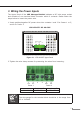
3. Wiring the Power Inputs The Upper Panel of the LRP Managed Switch indicates a DC inlet power socket and consists of one terminal block connector within 6 contacts. Please follow the steps below to insert the power wire. 1. Insert positive/negative DC power wires into contacts 1 and 2 for Power 1 or 5, and 6 for Power 2. LRP-422CST: DC 48~56V Input DC 48-56V DC1 Fault DC2 Figure 3-1: LRP-422CST Upper Panel 2. Tighten the wire-clamp screws for preventing the wires from loosening.
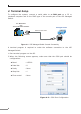
4. Terminal Setup To configure the system, connect a serial cable to a COM port on a PC or notebook computer and to the RJ45 type of the console port of the LRP Managed Switch. PC / Workstation with Terminal Emulation Software Managed Switch RS232 to RJ45 Cable Serial Port RJ45 Console Port Figure 4-1: LRP Managed Switch Console Connectivity A terminal program is required to make the software connection to the LRP Managed Switch. 1. Run terminal program on the OS. 2.
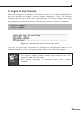
5. Logon to the Console Once the terminal is connected to the device, power on the LRP Managed Switch, and the terminal will display “running testing procedures”. Then, the following message asks to log-in user name and password. The factory default user name and password are shown as follows, and the login screen in Figure 5-1 appears. Username: admin Password: admin Figure 5-1: LRP Managed Switch Console Login Screen The user can now enter commands to manage the LRP Managed Switch.
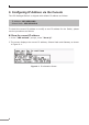
6. Configuring IP Address via the Console The LRP Managed Switch is shipped with default IP address as follows: IP Address: 192.168.0.100 Subnet Mask: 255.255.255.0 To check the current IP address or modify a new IP address for the Switch, please use the procedures as follows: Show the current IP address 1. At the “LRP-series#” prompt, enter “show ip”. 2. The screen displays the current IP address, Subnet Mask and Gateway as shown in Figure 6-1.
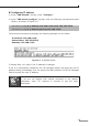
Configuring IP address 3. At the “LRP-series#” prompt, enter “configure”. 4. At the “LRP-series (config)#” prompt, enter the following command and press as shown in Figure 6-2. LRP-series (config)# ip address 192.168.1.100 mask 255.255.255.0 LRP-series (config)# ip default-gateway 192.168.1.254 The previous command would apply the following settings for the Switch. IP Address: 192.168.1.100 Subnet Mask: 255.255.255.0 Gateway: 192.168.1.254 Figure 6-2: IP Address Screen 5.
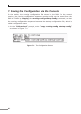
7. Saving the Configuration via the Console In the switch, the running configuration file stores in the RAM. In the current version, the running configuration sequence running-config can be saved from the RAM to FLASH by copying the running-config startup-config command, so that the running configuration sequence becomes the startup configuration file, which is called configuration save. 1. At the “LRP-series#” prompt, enter “copy running-config startup-config” as shown in Figure 7-1.
8. Starting Web Management The following shows how to start up the Web Management of the LRP Managed Switch. Note the LRP Managed Switch is configured through an Ethernet connection. Please make sure the manager PC must be set on the same IP subnet address. For example, the default IP address of the LRP Managed Switch is 192.168.0.100, then the manager PC should be set at 192.168.0.x (where x is a number between 1 and 254, except 100), and the default subnet mask is 255.255.255.0.
Logging in to the LRP Managed Switch 1. Use Internet Explorer 8.0 or above Web browser and enter IP address http://192.168.0.100 to access the Web interface. 2. When the following dialog box appears, please enter the default user name and password “admin”. The login screen in Figure 8-2 appears. Default Username: admin Default Password: admin Figure 8-2: Login Screen 3. After entering the password, the main screen appears as Figure 8-3 shows.
The Switch Menu on the left of the Web page lets you access all the commands and statistics the LRP Managed Switch provides. Figure 8-4: Switch Menu Now, you can use the Web management interface to continue the Switch management. Please refer to the user’s manual for more.
9. Starting Long Reach PoE Communication The following shows how to start up the Long Reach PoE Communication of the LRP Managed Switch from Web Management. Note The LRP Managed Switch is configured DISABLED Long Reach PoE function as default. Connect the Coaxial Cable 1. Insert the coaxial cable with one side being the 75ΩBNC plug connector into the Long Reach Ethernet coaxial interface. 2. Connect the other end of the cable to a device with Long Reach Ethernet coaxial extender installed. 3.
4. Enable Long Reach Power over Ethernet function for the all LRP ports from WebUI. 5. Check the LNK LED of the Long Reach Power over Ethernet interface on the front of the LRP Managed Switch. Ensure that the Long Reach Power over Ethernet interface is operating correctly. Note 1. Before installation, please consider the distance and watts value demand for PD devices. The LRP Managed Switch and LRP Extender PoE output capacity and upload/download performance depend on the length of coaxial cable.
Remove the connected Coaxial Cable 1. Make sure there is no network activity anymore. 2. Disable Long Reach Power over Ethernet function for all the LRP ports from WebUI. 3. Loosen the BNC male connector gently. 4. Pull out the coaxial cable gently.
Note Never pull out the coaxial cable without disabling Long Reach Power over Ethernet function for the port from WebUI. Directly pulling out the coaxial cable could damage the Long Reach Ethernet coaxial extender and the BNC female connector of the LRP Managed Switch. 1. The package contains warning stickers, which should be stuck on the coaxial cable connector before using PLANET LRP-422CST and LRP extender. If connected with a Non-PLANET LRP extender, it might cause damage to the equipment.
10. Saving Configuration via the Web In the LRP Managed Switch, the running configuration file stores in the RAM. In the current version, the running configuration sequence of running-config can be saved from the RAM to FLASH by “Save Configurations to FLASH” function, so that the running configuration sequence becomes the startup configuration file, which is called configuration save.
11. Recovering Back to Default Configuration IP Address has been changed or admin password has been forgotten – To reset the IP address to the default IP Address “192.168.0.100” or reset the login password to default value, press the hardware reset button on the front panel for about 10 seconds. After the device is rebooted, you can log in the management Web interface within the same subnet of 192.168.0.xx. RESET CAUTION The LRP interface is allowed to connect to LRP Extender only.
12. Customer Support Thank you for purchasing PLANET products. You can browse our online FAQ resource and User’s Manual on PLANET Web site first to check if it could solve your issue. If you need more support information, please contact PLANET switch support team. PLANET online FAQ: http://www.planet.com.tw/en/support/faq.php?type=1 Switch support team mail address: support_switch@planet.com.tw LRP-422CST User’s Manual: http://www.planet.com.tw/en/support/download.