
User's Manual

16
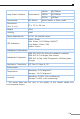
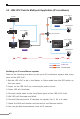
5.2 LRE-101C Point to Multi-point Application (IP surveillance)
Video
LRE-101C
Master
LRE-101C
Slave
5V DC adapter
Switch
Monitor
NVR
IP Camera
LRE-101C
Slave
5V DC adapter
5V DC adapter
IP Camera
BNC Tee Connector
100m100m 1600m
100BASE-TX UTP
Video Line
Video
Coaxial Cable
Coax.
Coax.
Coax.
Coax.
Building an IP surveillance system
Refer to the following procedure to set up an IP surveillance system with many
pairs of the LRE-101C:
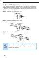
1.Set the LRE-101C to be in the Master or Slave mode from the DIP switch on
the rear panel.
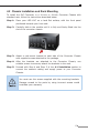
2. Power on the LRE-101C by connecting its power source.
3. Power LED will illuminate.
4. Connect coaxial cable to the Long Reach ports of two LRE-101C units.
5. LNK LED will illuminate and blink.
6. Connect Ethernet port to IP cameras via regular Cat. 5, 5e or 6 cable.
7. Install the NVR and monitor and connect to one Ethernet switch.
8. You can get data transmissions from all IP cameras.