-Port 10/100TX over UTP Long Reach Ethernet Extender LRE-101 User’s Manual
Trademarks Copyright © PLANET Technology Corp. 2022. Contents are subject to revision without prior notice. PLANET is a registered trademark of PLANET Technology Corp. trademarks belong to their respective owners.
ISEDC Statement CAN ICES-003(A) / NMB-003(A) This device complies with Industry Canada license-exempt RSS standard(s). Operation is subject to the following two conditions: (1) this device may not cause interference, and (2) this device must accept any interference, including interference that may cause undesired operation of the device. Le present appareil est conforme aux CNR d'Industrie Canada applicables aux appareils radio exempts de licence.
Table of Contents 1. Package Contents.................................................................................. 5 2. Hardware Introduction........................................................................... 6 2.1 Physical Dimensions........................................................................ 6 2.2 Front View..................................................................................... 7 2.3 Rear View..........................................................................
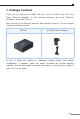
1. Package Contents Thank you for purchasing PLANET LRE-101 1-Port 10/100TX over UTP Long Reach Ethernet Extender. In the following sections, the term “Ethernet Extender” means the LRE-101. Open the box of the Ethernet Extender and carefully unpack it.
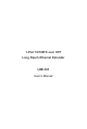
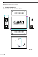
2. Hardware Introduction 2.1 Physical Dimensions Dimensions (W x D x H): 94 x 70.3 x 26.2mm 26.20 Slave Master Long Reach 70.30 LNK LNK/ ACT 10/100TX over UTP Extender LAN 10/100TX 5V DC Master PWR Long Reach Ethernet over UTP Extender LRE-101 Long Reach Ethernet 94.00 46.70 ∅ 7.
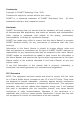
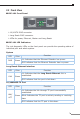
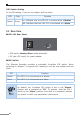
2.2 Front View LRE-101 Front Panel Long Reach LAN LNK LRE-101 Master PWR LNK/ ACT 10/100TX Long Reach Ethernet over UTP Extender 10/100TX RJ45 connector Long Reach RJ45 connector LEDs for power, Ethernet, Master and Long Reach LRE-101 LED Indicators The rich diagnostic LEDs on the front panel can provide the operating status of individual port and whole system. System LED PWR Function Color Green Lit: Indicates that the Ethernet Extender has power.
DIP Switch Setting In the PtP setting, it can be one master and one slave. LED Master Function Color Green Lit: Indicates that the LRE-101 is functioned as a Master. Off: Indicates that the LRE-101 is functioned as a Slave. 2.3 Rear View LRE-101 Rear Panel 5V DC Master Slave DIP switch: Master/Slave mode selectable DC jack (DC input) for power adapter DIP Switch The Ethernet Extender provides a selectable 2-position DIP switch.
2.4 Power Information The LRE-101 requires 5V DC, 2A power input, which conforms to the bundled AC adapter. Should you have the issue of power connection, contact your local sales representative. 2.5mm DC Receptacle 2.5mm +5V for each slot DC receptacle is 2.5mm wide that conforms to the Ethernet Extender 2.5mm DC jack’s central post. Do not install any improper unit.
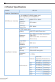
3. Product Specifications Product LRE-101 Hardware Specifications 1 10/100BASE-TX RJ45 Copper port, auto-negotiation/auto-MDI/MDI-X LAN Ethernet interface Cabling Cat5e UTP or above Maximum Distance 100 meters Maximum Frame Size 1522 bytes 1 RJ45 copper port Long Reach Interface Cabling Cat5 UTP cable Phone wire Maximum Distance Max.
Functionality DIP Switch Dimensions (W x D x H) Select Master or Slave mode 97 x 70.3 x 26 mm Weight 194g Housing Metal Power Requirement 5V DC, 2A external power LED Indicators Power: Green LAN: Green, 10/100Mbps LNK/ACT Long Reach: Green, LNK Master: Green Standards Conformance Standards Compliance IEEE 802.3/802.3u Ethernet standard compliant IEEE 802.3x Full-duplex flow control IEEE 802.
4. Installations 4.1 Wall-mount Installation Step 1: Find a suitable wall to mount the LRE-101. Step 2: Screw two screws on the wall. Step 3: Hang the LRE-101 on the screws from the wall. Step 4: Repeat Step 5 of Desktop Installation for power supply to the LRE-101. 5V DC 10GBASE-T to 10GBASE -X Before mounting the device to the wall, please check the location of the electrical outlet and the length of the Ethernet cable.
4.2 Chassis Installation and Rack Mounting To install the Ethernet Extender in a 10-inch or 19-inch Converter Chassis with standard rack, follow the instructions described below. Step 1: Place your LRE-101 on a hard flat surface, with the front panel positioned towards your front side. Step 2: Carefully slide in the module until it is fully and firmly fitted into the slot of the converter chassis.
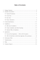
4.3 Optional DIN-rail Installation There are two DIN-rail holes on the left side of the LRE-101 that allows to be easily installed by DIN-rail mounting. PLANET optional DIN-rail mounting kit – RKE-DIN -- can be ordered separately. Refer to the following steps for the DIN-rail mounting of the LRE-101: Step 1: Screw the DIN rail on the LRE-101. Step 2: Now slide the DIN rail into the track. Step 3: Check whether the DIN rail is tightly on the track.
5. Applications The Ethernet Extender does not require any software configuration. Users can immediately use any feature of this product simply by attaching the cables and turning the power on. There are some key limitations on the Ethernet Extender. Please check the following items. 5.1 Point-to-Point Application -- LAN to LAN Connection One set of the Ethernet Extender could be used to link two local area networks that are located in different places.
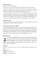
5.2 LRE-101 Multi-Point to Multi-Point Application (IP surveillance) Ethernet Switch NVR Video DC DC LRE-101 LRE-101 Master Master Monitor 700m 1200m DC LRE-101 Slave IP Camera DC Video DC Video Line Power Line (DC) LRE-101 Slave IP Camera 100BASE-TX UTP Telephone wire Building an IP surveillance system Refer to the following procedure to set up an IP surveillance system with many pairs of the LRE-101: 1.
6. Performance Table LRE-101 Upstream/Downstream Performance Phone wire Distance (meter) (Upstream/Downstream) Unit: Mbps 200 81 80 400 59 52 600 52 44 800 28 22 1000 48 36 1200 11 6 Cat5 Distance (meter) (Upstream/Downstream) Unit: Mbps 200 89 88 400 60 58 600 29 29 800 14 33 *** The actual data rate will vary in the quality of the UTP cables or Phone wire and environmental factors.
7. Troubleshooting SYMPTOM: LNK LED does not light up after wire is connected to the Long Reach port. CHECKPOINT: Please note you must use one LRE-101 in Master mode and the other LRE-101 in Slave mode to make connection to each other work. SYMPTOM: TP LED does not light after cable is connected to the port. CHECKPOINT: 1.Verify you are using the Cat5e or better cable with RJ45 connector to connect to the port. 2.
8. FAQs Q1: What is the best distance for LRE-101? A1: In order to guarantee the stability and better quality of network, we suggest the distance should not exceed 700m (Cat.5 UTP) and 1200m (Phone wire).
9. Customer Support Thank you for purchasing PLANET products. You can browse our online FAQ resource and User’s Manual on PLANET Web site first to check if it could solve your issue. If you need more support information, please contact PLANET switch support team. PLANET online FAQs: https://www.planet.com.tw/en/support/faq Switch support team mail address: support@planet.com.tw Copyright © PLANET Technology Corp. 2022. Contents are subject to revision without prior notice.