Trademarks Copyright PLANET Technology Corp. 2002. Contents subject to revision without prior notice. PLANET is a registered trademark of PLANET Technology Corp. The information in this manual is subject to change without notice. All other trademarks belong to their respective owners. FCC Warning This equipment has been tested and found to comply with the regulations for a Class A digital device, pursuant to Part 15 of the FCC Rules.
Table of Contents Chapter 1 INTRODUCTION 1 1.1 Briefing 1 1.2 Features 1 Chapter 2 UNPACKING AND INSTALL 3 2.1 Unpacking 3 2.2 Installation 3 2.3 Deciding How to Install the System 3 Chapter 3 IDENTIFYING FRONT PANEL 7 3.1 Front Panel 7 3.2 LED Indicators 7 Chapter 4 CONFIGURING THE SYSTEM 9 4.1 Configure Through Terminal Emulator/TELNET Program 4.
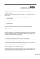
Chapter 1 Introduction 1.1 Briefing The Intelligent Media Converter Chassis WMC-1600R series provides 16-slot and one management system in the 19”-rack chassis. The management function enable network administrator to monitor the media converter connection status and configure the converter via SNMP agent, Telnet and Web remotely or via RS-232 console port, yet eases the maintenance of media conversion.
2
Chapter 2 UNPACKING AND INSTALL This chapter provides unpacking and setup information for the Media Converter Chassis. 2.1 Unpacking Open the box of the WMC-1600R and carefully unpack it. The box should contain the following items: • One Intelligent Media Converter Chassis with one power supply installed • One RS-232 Cable • One Power Cord • CD-ROM • Rack mounting Kit • This User’s Manual If any item is found missing or damaged, please contact your local reseller for replacement. 2.
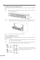
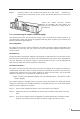
2.3.1 Mounted to 19-inch standard rack Use the rack-mount brackets and screws to install the chassis into any EIA 19" standard rack. Step 1: Attach the brackets to each side of the chassis. Apply four screws to each side and secure them tightly. Step 2: Carefully position the chassis into the rack. Align the brackets to the side holes on the rack and use rack screws to secure the chassis with the rack. Step 3: Proceed to the “Connecting to Power” section. 2.3.
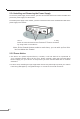
Step 3: Carefully slide in the module and fasten the hand screw clockwise by using hand or screwdriver until it is fully and firmly fitted into the slot of the chassis. Insert the media converter module into an available slot and fasten the hand screw clockwise by using hand or screwdriver. 2.3.3 Connecting to Power (Power Supply) The chassis ships with only one power supply, and a second power supply option is at your discretion.
2.3.4 Installing and Removing the Power Supply To remove a power supply out the chassis, you have to loose the hand screw counter clockwise and pull out the power supply from the chassis. To install a power supply to the chassis, you have to fasten the hand screw clockwise and slide in the power supply to the chassis. You can slide in and out the power supply from the bay, fasten or loose the hand screw clockwise or counter clockwise by using hand or screwdriver.
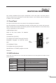
Chapter 3 IDENTIFYING FRONT PANEL This section identifies all the major components of the front panel. The front panel is shown, followed by a description of each panel feature. The indicator panel is described in detail in the next chapter. 3.1 Front Panel The figure below shows the front panels of the Management Module. The LED indicators of the Management Module include Power On, Power Fail, Fan Fail, MGM, Console and Link/ACT.
8
Chapter 4 CONFIGURING THE SYSTEM This chapter provides network managers and system administrators with information about how to configure the WMC-1600R via the Management interface. 4.1 Configure Through Terminal Emulator/TELNET Program 4.1.1 Console and Terminal Emulator program setting The WMC-1600R can be accessible using a terminal or terminal emulator attached to the RS-232 serial port. 1.Locate correct DB9 serial port cable with female DB9 connector. 2.
4.1.3 Management Setting Through Terminal Emulator There are three items in the Main Menu, System Function, Configuration and SNMP Configuration. 4.1.3.1 System Function There are three items in System Function menu, “Software Reboot, Factory Reset, and Image Update. 4.1.3.1.1 Software Reboot After configuring, it needs to reboot the software setting in order to run the device properly. 4.1.3.1.2 Factory Reset This function is to set the device back to the default setting in case of the messy setting. 4.
There are four items in the Configuration menu, “General Configuration, System Configuration, Media Converter Chassis and Media Converters. 4.1.3.2.1 General Configuration Hardware revision: noted the version of the hardware. BIOS revision: noted the version of the BIOS. Firmware revision: noted the version of the firmware. Change Password: the changing of the admit password. Confirm Password: to confirm the setting of admit password. System Name: to authorize the device system name.
4.1.3.2.3 Media Converter Chassis The screen will show out the power status of the WMC-1600R. V stands for “yes” and X stands for “No”. Plug in: indicates if Power 1 or 2 was plugged in or not. Power Fail: indicates if the Power 1 or 2 is fail or not. Fan Fail: indicates if the Fan 1 or 2 is fail or not. 4.1.3.2.4 Media Converters Indicates the Link, Duplex mode, Speed and Fail status of each media converter. 4.1.3.2.
Device LLCF: Link Loss Carry Forward, “on” or “off”. Enable: to enable the link of the Device, “on” or “off”. Media 1 LLR: Link Loss Return, “on” or “off”. Auto: “A” for Auto-Negotiation or “F” for “forced Mode”. Speed: to select the speed of the copper port, “10M”, “100M” or “1G”. Dup: Duplex mode, “F” for Full Duplex or “H” for Half Duplex. FC: Flow Control, “on” or “off”. Enable: to enable the link of the Media 1, “on” or “off”. Media 2 LLR: Link Loss Return, “on” or “off”.
4.1.3.3 SNMP Configuration Get Community Name: to get the device community name (default = public). Set Community Name: to set the device community name (default = private). Trap Community Name: to authorize the device trap community name (default = public). Trap Host IP Address: to set the trap host IP address (same as monitoring station IP address). Cold Start trap: to set the trap for rebooting the device (default = enable).
4.2 Management through Web browser The WMC-1600R is accessible using a Web browser (IE explorer, Netscape Communications, etc.) to open up the chassis monitoring system. The default IP Address for the chassis system is “192.168.1.1”, and the default Login name and password is both “root”. After enter its web interface, the Home Page will show out the page for general configuration.
4.2.1 System Function There are four items in System Function menu, “Software Reboot, Factory Reset, Image Update and Configuration Update. 4.2.1.1 Software Reboot Reboot the management module in order to run the new setting properly. 4.2.1.2 Factory Reset This function is to set the device back to the default setting in case of the messy setting. 4.2.1.3 Image Update The section is to set the TFTP Server IP Address first, and the default address was set to “192.168.1.2”.
System Name: to authorize the device system name. Location: to show the WMC-1600R where it is located. Refresh time: to set the refreshing time of the device through the web. NOTE: After configuring the system device, need to press the save button to save the setting. 4.2.2.2 System Configuration MAC Address: will show out the MAC address of the Management interface. IP Address: to allocate an IP address for the Management interface, the default IP is “192.168.1.1”.
Warm Start trap: to set the trap when the device had been reset (default = enable). Authentication Fail Trap: to set the warning trap when the community name of the device and workstation are different (default = enable). Power Fail Trap: to set the Power Fail Trap (default = enable). Fan Fail Trap: to set the Fan fail trap (default = enable). MC Plug-in Trap: to set the trap when a Media Converter Module has been plugged in (default = enable).
4.2.2.5 Redundant Backup Setting The redundant function is to change the master line to the slave line in case of the linking fails happen. The Redundant functions were set fixed, the master slot is slot 1(odd number slot) and the slave slot is slot 2(even number slot), and there are eight redundant groups in all. The “Act” will indicate what slot is active. When the slave slot is active, and we need to transfer again to the master slot, we need to push on the restart button.
20
Chapter 5 TECHNICAL SPECIFICATIONS Capacity Material Chassis System Sixteen bays for housing up to sixteen media converters Steel One power supply provided, hot-swappable Power *A second power supply for load-sharing is optional, also hot- Cooling Dimensions Net Weight swappable Two fans mounted together with the power supply or alone at the rear W415 mm × D 390mm × H89 mmStandard 19” size, 2 U 7.2kg approx.
Management Module IEEE802.3 10Base-T Ethernet Standards IEEE802.3u 100 Base-TX Fast Ethernet Protocol Data IEEE802.3x flow control CSMA/CD Ethernet: 10Mbps (half duplex), 20Mbps (full duplex)Fast Transfer Rate LED Indicators Cable Fixed Ports Power Consumption Temperature Humidity Emissions 22 Ethernet: 100Mbps (half duplex), 200Mbps (full duplex) Power On, Power Fail, Fan Fail, MGM, Console, LNK/ACT 10BaseT: 2-pair UTP Cat. 3,4,5; EIA/TIA- 568 100-ohm STP 100Base-TX: 2-pair UTP Cat.
Part No.