
User's Manual

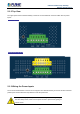


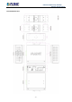


Table Of Contents

Industrial VPN Security Gateway
IVR-100_IVR-300 Series
- 21 -
LED Definition:
LED Color Function
P1 Green Lights to indicate DC power input 1 has power.
P2
Green
Lights to indicate DC power input 2 has power.
Alarm Red Lights to indicate the either power or port fail
I/O Red Indicate Condition of Digital Input or Digital Output has triggered.
2.4G Green Lights up when 2.4G Wi-Fi service is enabled (for IVR-300W)
5G Green Lights up when 5G Wi-Fi service is enabled (for IVR-300W)
1000
LNK/ACT
Green
Lights
Indicates the link through that port is successfully established at 1000Mbps
Blinks
Indicates that the Switch is actively sending or receiving data over that port.
100
LNK/ACT
Amber
Lights Indicates the link through that port is successfully established at 100Mbps.
Blinks
Indicates that the Switch is actively sending or receiving data over that port.
Ports
USB Port
USB 3.0 port for system configuration backup and restoration.
Reset Button
Power on the device and press the reset button for less than 5 seconds to
reboot it or over 5 seconds to restore it to factory default settings.
Serial Interface
1 x 3-pin terminal block for RS485
Gigabit Ports 1-3
It is a LAN port for connecting to a switch.
Gigabit Port 4
Default is LAN port. It can be defined as LAN port or WAN port.
Gigabit Port 5
It is a WAN port for connecting to a perimeter gateway.