Industrial VPN Security Gateway IVR-100_IVR-300 Series Industrial 5-Port 10/100/1000T VPN Security Gateway IVR-100 & IVR-300 Series -1-
Industrial VPN Security Gateway IVR-100_IVR-300 Series Copyright Copyright (C) 2022 PLANET Technology Corp. All rights reserved. The products and programs described in this User’s Manual are licensed products of PLANET Technology, This User’s Manual contains proprietary information protected by copyright, and this User’s Manual and all accompanying hardware, software, and documentation are copyrighted.
Industrial VPN Security Gateway IVR-100_IVR-300 Series – Connect the equipment into an outlet on a circuit different from that to which the receiver is connected. – Consult the dealer or an experienced radio/TV technician for help. CE mark Warning The is a class A device, In a domestic environment, this product may cause radio interference, in which case the user may be required to take adequate measures.
Industrial VPN Security Gateway IVR-100_IVR-300 Series Table of Contents Chapter 1. Product Introduction ........................................................................................................ 7 1.1 Package Contents ................................................................................................................. 7 1.2 Overview ............................................................................................................................... 8 1.
Industrial VPN Security Gateway IVR-100_IVR-300 Series 4.5 4.6 4.7 4.4.7 High Availability ................................................................................................. 61 4.4.8 RADIUS............................................................................................................. 63 4.4.9 Captive Portal ................................................................................................... 65 4.4.10 SNMP ................................................
Industrial VPN Security Gateway IVR-100_IVR-300 Series 4.8 4.9 4.7.7 Certificates ...................................................................................................... 111 4.7.8 VPN Connection ............................................................................................. 111 4.7.9 SD WAN .......................................................................................................... 112 AP Control ............................................................
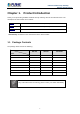
Industrial VPN Security Gateway IVR-100_IVR-300 Series Chapter 1. Product Introduction Thank you for purchasing PLANET Industrial Security Gateway, IVR-100 and IVR-300 series. The descriptions of these models are as follows IVR-100 Industrial 5-Port 10/100/1000T VPN Security Gateway IVR-300 Industrial 5-Port 10/100/1000T VPN Security Gateway with Redundant Power IVR-300W Industrial 5-Port 10/100/1000T + 802.
Industrial VPN Security Gateway IVR-100_IVR-300 Series 1.2 Overview Powerful Industrial VPN Security Solution PLANET has launched the IVR-100 and IVR-300 Series Security Gateway for demanding applications. It features five Ethernet ports (4 LANs and 1 WAN), IEEE 11ax Wi-Fi capability (for IVR-300W), RS485 serial port (for IVR-300 / IVR-300W, and DI and DO interfaces. Incorporating SD-WAN function, it can greatly increase WAN optimization for multiple WAN links to be managed.
Industrial VPN Security Gateway IVR-100_IVR-300 Series Ideal VPN Security Gateway Solution for Factories and Transportations The IVR-100 and IVR-300 Series provides complete data security and privacy for accessing and exchanging the most sensitive data, built-in IPSec VPN function with DES/3DES/AES encryption and MD5/SHA-1/SHA-256/SHA-384/SHA-512 authentication, and GRE, SSL, PPTP and L2TP server mechanism.
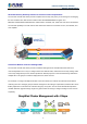
Industrial VPN Security Gateway IVR-100_IVR-300 Series Wi-Fi Deployments and Authentication with Simplified Management (for IVR-300 Series) The IVR-300 Series also provides a built-in AP Controller, Captive Portal, RADIUS and a DHCP server to facilitate small and medium businesses to deploy secure employee and guest access services without any additional server. The IVR-300 Series can offer a secure Wi-Fi network with easy installation for your business.
Industrial VPN Security Gateway IVR-100_IVR-300 Series facility. IVR-100 and IVR-300 Series supports SNMP and it can be managed via any management software based on the standard SNMP protocol. Cost-effective Solution for RS-485 to Ethernet Application (for IVR-300 Series.) The IVR-100 and IVR-300 Series provides a feature that can convert the Serial RS-485 communication to IP networking. Ethernet signal allows two types of segments to connect easily, efficiently and inexpensively.
Industrial VPN Security Gateway IVR-100_IVR-300 Series - 12 -
Industrial VPN Security Gateway IVR-100_IVR-300 Series 1.3 Features Hardware 5 10/100/1000BASE-T RJ45 ports 1 undefined Ethernet port (LAN/WAN) Dual-WAN function 1 USB 3.0 port for system configuration backup and firmware upgrade 1 reset button 1 3-pin terminal block (RS485) (for IVR-300 Series) DIDO (for IVR-300 Series) RF Interface Characteristics (for IVR-300W) Features 2.4GHz (802.11b/g/n/ax) and 5GHz (802.
Industrial VPN Security Gateway IVR-100_IVR-300 Series VPN Features IPSec/Remote Server (Net-to-Net, Host-to-Net), GRE, PPTP Server, L2TP Server, SSL Server/Client (Open VPN) Max.
Industrial VPN Security Gateway IVR-100_IVR-300 Series 1.4 Product Specifications IVR-100 Product IVR-300 IVR-300W Hardware Specifications 5 10/100/1000BASE-T RJ45 Ethernet ports including 3 LAN ports (Ports 1 to 3) Copper Ports 1 LAN/WAN port (Port 4) 1 WAN port (Port 5) USB Port 1 USB 3.0 port 1 USB 3.0 port Wireless Connector - - Wireless Antenna - - Serial Interface - 1 USB 3.
Industrial VPN Security Gateway IVR-100_IVR-300 Series Ethernet Interfaces Ethernet Interfaces Ethernet Interfaces (Ports 1-4 and WAN (Ports 1-4 and WAN (Ports 1-4 and WAN Port): Port): Port): 1000 LNK/ACT 1000 LNK/ACT 1000 LNK/ACT (Green) (Green) (Green) 10/100 LNK/ACT 10/100 LNK/ACT 10/100 LNK/ACT (Amber) (Amber) (Amber) Wi-Fi: 2.
Industrial VPN Security Gateway IVR-100_IVR-300 Series Temperature: -40 ~ 85 degrees C Storage Relative humidity: 5 ~ 90% (non-condensing) Wireless Specification for IVR-300W Model Wireless IEEE 802.11a/n/ac/ax 5GHz Standard IEEE 802.11g/b/n/ax 2.4GHz Band Mode 2.4G & 5G concurrent mode Antenna 5 dBi external antennas with SMA connectors for Wi-Fi 2.4GHz Frequency Range 5GHz 2.4GHz America FCC: 2.412~2.462GHz Europe ETSI: 2.412GHz~2.472GHz 5.15GHz ~5.
Industrial VPN Security Gateway IVR-100_IVR-300 Series 11ac HT80: 14.5+/-1.5dBm @MCS9 11ax HT20: 20+/-1.5dBm @MCS9 11ax HT40: 17 +/- 1.5dBm @MCS9 11ax HT80: 14.5 +/- 1.5dBm @MCS11 WEP (64/128-bit) encryption security WPA / WPA2 (TKIP/AES) Encryption Security WPA-PSK / WPA2-PSK (TKIP/AES) / WPA3-PSK (TKIP/AES) 802.
Industrial VPN Security Gateway IVR-100_IVR-300 Series Chapter 2. Hardware Introduction 2.1 Physical Descriptions 2.1.1 Front View IVR-100 Front Panel LED Color P1 Green P2 Green Fault Red 1000 LNK/ACT Lights to indicate DC power input 1 has power. Lights to indicate DC power input 2 has power.
Industrial VPN Security Gateway IVR-100_IVR-300 Series Ports USB Port USB 3.0 port for system configuration backup and restoration. Power on the device and press the reset button for less than 5 seconds to Reset Button reboot it or over 5 seconds to restore it to factory default settings. Gigabit Ports 1-3 It is a LAN port for connecting to a switch. Gigabit Port 4 Default is LAN port. It can be defined as LAN port or WAN port. Gigabit Port 5 It is a WAN port for connecting to a perimeter gateway.
Industrial VPN Security Gateway IVR-100_IVR-300 Series LED Definition: LED Color Function P1 Green Lights to indicate DC power input 1 has power. P2 Green Lights to indicate DC power input 2 has power. Alarm Red Lights to indicate the either power or port fail I/O Red Indicate Condition of Digital Input or Digital Output has triggered. 2.4G Green Lights up when 2.
Industrial VPN Security Gateway IVR-100_IVR-300 Series 2.1.2 Top View The upper panel of the Industrial Gateway consists of one terminal block connector within two DC power inputs. IVR-100 Top View IVR-300 Series Top View 2.1.3 Wiring the Power Inputs The 6-contact terminal block connector on the top panel of Industrial Gateway is used for two DC redundant power inputs. Please follow the steps below to insert the power wire.
Industrial VPN Security Gateway IVR-100_IVR-300 Series 1. Insert positive and negative DC power wires into contacts 1 and 2 for POWER 1, or 5 and 6 for POWER 2.v To avoid damage, please use the Industrial Gateway under its specification. 2. Tighten the wire-clamp screws for preventing the wires from loosening. 1 2 Power 1 + - 3 4 Alarm 5 6 Power 2 + - The wire gauge for the terminal block should be in the range from 12 to 24 AWG.
Industrial VPN Security Gateway IVR-100_IVR-300 Series 2.1.4 Wiring the Fault Alarm Contact The fault alarm contacts are in the middle of the terminal block connector as the picture shows below. Inserting the wires, the Industrial Gateway will detect the fault status of the power failure and then forms an open circuit. The following illustration shows an application example for wiring the fault alarm contacts. 1 2 3 4 5 6 Insert the wires into the fault alarm contacts 1.
Industrial VPN Security Gateway IVR-100_IVR-300 Series 2.1.
Industrial VPN Security Gateway IVR-100_IVR-300 Series IVR-300 Dimensions - 26 -
Industrial VPN Security Gateway IVR-100_IVR-300 Series IVR-300W Dimensions - 27 -
Industrial VPN Security Gateway IVR-100_IVR-300 Series 2.2 Hardware Installation This section describes how to install the Industrial Gateway. There are three methods to install the Industrial Gateway -- DIN-rail mounting, wall mounting and side wall mounting. Basic knowledge of networking is assumed. Please read the following sections and perform the procedures in the order being presented. (The device shown on this chapter is just a representation of the said device.) 2.2.
Industrial VPN Security Gateway IVR-100_IVR-300 Series Step 3: Connect your device to hub / switch. A. Connect one end of a standard network cable to the LAN port (port 1) of the device. B. Connect the other end of the cable to the hub / switch. The UTP Category 5, 5e or 6 network cabling with RJ45 tips is recommended. Step 4: Connect your device to internet. A. Connect one end of a standard network cable to the WAN port (port 5) of the device. B.
Industrial VPN Security Gateway IVR-100_IVR-300 Series Step 3: Use the hook holes at the corners of the wall mount plate to hang the Industrial Gateway on the wall. Step 4: To remove the wall mount plate, reverse the steps above. Step 5: Proceed with Steps 3, 4 and 5 in Section 2.2.1 DIN-rail Mounting to connect the network cabling and power on the device.
Industrial VPN Security Gateway IVR-100_IVR-300 Series 2.2.3 Side Wall Mount Plate Mounting To install the Industrial Gateway on the wall, please follow the instructions below. Step 1: Remove the DIN-rail from the Industrial Gateway. Use the screwdriver to loosen the screws to remove the DIN-rail. Step 2: Place the wall-mount plate on the side panel and use the screwdriver to screw the wall mount plate tightly on the Industrial Gateway.
Industrial VPN Security Gateway IVR-100_IVR-300 Series 2.2.4 Wi-Fi Antenna Installation (For IVR-300W only) Step 1: Fasten the two dual-band antennas to the antenna connectors on the front panel of the IVR-300W. Step 2: You can bend the antennas to fit your actual needs.
Industrial VPN Security Gateway IVR-100_IVR-300 Series Chapter 3. Preparation Before getting into the device’s web UI, user has to check the network setting and configure PC’s IP address. 3.1 Requirements User is able to confirm the following items before configuration: 1. Please confirm the network is working properly; it is strongly suggested to test your network connection by connecting your computer directly to ISP. 2. Suggested operating systems: Windows 7 / 8 / 10. 3.
Industrial VPN Security Gateway IVR-100_IVR-300 Series 2. Click "Change adapter settings". 3. Right-click on the Local Area Connection and select Properties.
Industrial VPN Security Gateway IVR-100_IVR-300 Series 4. Select Internet Protocol Version 4 (TCP/IPv4) and click Properties or directly double-click on Internet Protocol Version 4 (TCP/IPv4).
Industrial VPN Security Gateway IVR-100_IVR-300 Series 5. Select "Use the following IP address" and "Obtain DNS server address automatically", and then click the “OK” button.
Industrial VPN Security Gateway IVR-100_IVR-300 Series 3.2.2 Windows 10 If you are using Windows 10, please refer to the following: 1. In the search box on the taskbar, type “View network connections”, and then select View network connections at the top of the list.
Industrial VPN Security Gateway IVR-100_IVR-300 Series 2. Right-click on the Local Area Connection and select Properties. 3. Select Internet Protocol Version 4 (TCP/IPv4) and click Properties or directly double-click on Internet Protocol Version 4 (TCP/IPv4).
Industrial VPN Security Gateway IVR-100_IVR-300 Series 4. Select "Use the following IP address" and "Obtain DNS server address automatically", and then click the “OK” button. 3.3 Planet Smart Discovery Utility For easily listing the Gateway in your Ethernet environment, the search tool -- Planet Smart Discovery Utility -is an ideal solution. The following installation instructions are to guide you to running the Planet Smart Discovery Utility. 1.
Industrial VPN Security Gateway IVR-100_IVR-300 Series Figure: Planet Smart Discovery Utility Screen If there are two LAN cards or above in the same administrator PC, choose a different LAN card by using the “Select Adapter” tool. 3. Press the “Refresh” button for the currently connected devices in the discovery list as the screen shows below: Figure: Planet Smart Discovery Utility Screen 1.
Industrial VPN Security Gateway IVR-100_IVR-300 Series Update Multi: use current setting on choose multi-devices. Update All: use current setting on whole devices in the list. The same functions mentioned above also can be found in “Option” tools bar. 3. To click the “Control Packet Force Broadcast” function, it allows you to assign a new setting value to the device under a different IP subnet address. 4. Press the “Connect to Device” button and the Web login screen appears.
Industrial VPN Security Gateway IVR-100_IVR-300 Series Chapter 4. Web-based Management This chapter provides setup details of the device’s Web-based Interface. 4.1 Introduction The device can be configured with your Web browser. Before configuring, please make sure your PC is under the same IP segment with the device. 4.2 Logging in to the VPN Gateway Refer to the steps below to configure the VPN Gateway: Step 1.
Industrial VPN Security Gateway IVR-100_IVR-300 Series Web Login Screen as below: Please follow the wizard to do the first-time account modification.
Industrial VPN Security Gateway IVR-100_IVR-300 Series Figure Web Main Screen Now, you can use the Web management interface to continue the Security Gateway management or manage the Security Gateway by console interface. Please refer to the user’s manual for more. Administrators are strongly suggested to change the default password and Wi-Fi SSID on the first login to safeguard system security. 1. For security reason, please change and memorize the new password after this first setup. 2.
Industrial VPN Security Gateway IVR-100_IVR-300 Series Web Panel Main Menu Figure: Main Web Page Function Menu ■ Web Panel The web panel displays the device’s ports as shown below. Figure: Web Panel Object Icon Function To indicate the port without the RJ45 plug-in. Ethernet port To indicate network data is sending or receiving. ■ Main Menu The main menu displays the product name, function menu, and main information in the center.
Industrial VPN Security Gateway IVR-100_IVR-300 Series Object Description System Provides System information of the Gateway. Network Provides WAN, LAN and network configurations of the Gateway. Security Provides Firewall and security configurations of the Gateway. VPN Provides VPN configuration of the Gateway.
Industrial VPN Security Gateway IVR-100_IVR-300 Series Figure: System Menu Object Wizard Description The Wizard will guide the user to configuring the Gateway easily and quickly. Dashboard The overview of system information includes connection, port, and system status. System Status Display the status of the system, Device Information, LAN and WAN.
Industrial VPN Security Gateway IVR-100_IVR-300 Series SNMP Display SNMP system information NMS Enable/Disable NMS on VPN Security Gateway Fault Alarm One relay output for power failure.
Industrial VPN Security Gateway IVR-100_IVR-300 Series 4.4.1 Wizard The Wizard will guide the user to configuring the Gateway easily and quickly. There are different procedures in different operation modes. According to the operation mode you switch to, please follow the instructions below to configure the Gateway via Setup Wizard as shown below Figure: Setup Wizard Step 1: Account Modification Set up the Username and Password for the Account Modification as shown below.
Industrial VPN Security Gateway IVR-100_IVR-300 Series Object IP Address Description Enter the IP address of your VPN Security Gateway The default is 192.168.1.1. Subnet Mask An address code that determines the size of the network. Normally use 255.255.255.0 as the subnet mask. DHCP Server By default, the DHCP Server is enabled. If user needs to disable the function, please uncheck the box. By default, the start IP address is 192.168.1.100.
Industrial VPN Security Gateway IVR-100_IVR-300 Series Mode 1 -- Static IP Select Static IP Address if all the Internet port’s IP information is provided to you by your ISP. You will need to enter the IP Address, Netmask, Default Gateway and DNS Server provided to you by your ISP. Each IP address entered in the fields must be in the appropriate IP form, which are four octets separated by a dot (x.x.x.x). The VPN Security Gateway will not accept the IP address if it is not in this format.
Industrial VPN Security Gateway IVR-100_IVR-300 Series Figure: WAN Interface Setup – DHCP Setup Step 4: Wireless Setting (For IVR-300W only) Set up the Wireless Settings as shown below.
Industrial VPN Security Gateway IVR-100_IVR-300 Series Object Description 2.4G Wireless Status Allows user to enable or disable 2.4G Wi-Fi Wireless Name (SSID) It is the wireless network name. The default 2.4G SSID is “PLANET_2.4G” Hide SSID Allows user to enable or disable SSID Bandwidth Select the operating channel width, “20MHz” or “40MHz” Channel It shows the channel of the CPE. Default 2.4GHz is channel 6. Encryption Select the wireless encryption.
Industrial VPN Security Gateway IVR-100_IVR-300 Series Object Description The SPI Firewall prevents attack and improper access to network SPI Firewall resources. The default configuration is enabled. SYN Flood is a popular attack way. DoS and DDoS are TCP protocols. Block SYN Flood Hackers like to use this method to make a fake connection that involves the CPU, memory, and so on. The default configuration is enabled.
Industrial VPN Security Gateway IVR-100_IVR-300 Series Object Description Finish Press this button to save and apply changes. Previous Press this button for the previous step.
Industrial VPN Security Gateway IVR-100_IVR-300 Series 4.4.2 Dashboard The dashboard provides an overview of system information including connection, port, and system status. The setup is shown below. Figure: Dashboard WAN/LAN Connection Status Object Description The status means WAN is connected to Internet and LAN is connected. The status means WAN is disconnected to Internet and LAN is connected.
Industrial VPN Security Gateway IVR-100_IVR-300 Series The status means WAN is connected to Internet and LAN is disconnected. Port Status Object Description Ethernet port is in use. Ethernet port is not in use. USB port is in use. USB port is not in use. System Information Object Description Display the CPU loading Display the memory usage Wireless Status Object Description Wireless is in use. Wireless is not in use.
Industrial VPN Security Gateway IVR-100_IVR-300 Series 4.4.3 Status This page displays system information as shown below.
Industrial VPN Security Gateway IVR-100_IVR-300 Series Figure: Status 4.4.4 System Service This page displays system service information as shown below.
Industrial VPN Security Gateway IVR-100_IVR-300 Series Figure: System Service 4.4.5 Statistics This page displays the number of packets that pass through the VPN Security Gateway on the WAN and LAN. The statistics are shown below.
Industrial VPN Security Gateway IVR-100_IVR-300 Series 4.4.6 Connection Status The page will show the DHCP Table and ARP Table. The status is shown below. Figure: Connection Status 4.4.7 High Availability High Availability (HA) is a redundant system that two IVR VPN Security Gateways can be set up in a master/slave configuration.
Industrial VPN Security Gateway IVR-100_IVR-300 Series The page will show the High Availability configuration. The High Availability page is shown below. Figure: High Availability Object High Availability Description Disable or enable the High Availability function. The default configuration is disabled. Username Create the username for the HA. Password Create the password for the HA. Mode Choose Master or Slave role. Virtual IP Address Assign an IP address as a virtual IP.
Industrial VPN Security Gateway IVR-100_IVR-300 Series 4.4.8 RADIUS Remote Authentication Dial-In User Service (RADIUS) is a security authentication client/server protocol that supports authentication, authorization and accounting. The RADIUS Server page is shown below. Figure: RADIUS Server Object RADIUS Description Disable or enable the RADIUS function. The default configuration is disabled.
Industrial VPN Security Gateway IVR-100_IVR-300 Series The RADIUS client page is shown below. Figure: RADIUS Client Object Description Name Describe client’s name Client IP address Describe client’s IP address Secret Key The RADIUS server and client share a secret key that is used to authenticate the messages sent between server and client.
Industrial VPN Security Gateway IVR-100_IVR-300 Series 4.4.9 Captive Portal Captive portal service gives the ability to organize a public (or guest) Wi-Fi zone with user authorization. A captive portal is the authorization page that forcibly redirects users who connect to the public network before accessing the Internet. The Captive portal page is shown below. Figure: Captive portal Object Captive portal Description Disable or enable the Captive portal function. The default configuration is disabled.
Industrial VPN Security Gateway IVR-100_IVR-300 Series 4.4.10 SNMP This page provides SNMP setting as shown below. Figure: CloudViewer Server – Internet Configuration Page Object Enable SNMP Description Disable or enable the SNMP function. The default configuration is enabled.
Industrial VPN Security Gateway IVR-100_IVR-300 Series 4.4.11 NMS The IVR series can support both NMS controller and CloudViewer Sever for remote management. PLANET's NMS Controller is a Network Management System that can monitor all kinds of deployed network devices, such as managed switches, media converters, routers, smart APs, VoIP phones, IP cameras, etc., compliant with the SNMP Protocol, ONVIF Protocol and PLANET Smart Discovery utility.
Industrial VPN Security Gateway IVR-100_IVR-300 Series The CloudViewer Server – Internet screen appears as shown below.
Industrial VPN Security Gateway IVR-100_IVR-300 Series 4.4.12 Fault Alarm The IVR series supports a Fault Alarm feature which can alert the users when there is something wrong with the device. With this ideal feature, the users would not have to waste time finding where the issue is. It will help to save time and human resource. This page provides fault alarm setting as shown below. Figure: Fault Alarm Object Description • Enable Controls whether Fault Alarm is enabled.
Industrial VPN Security Gateway IVR-100_IVR-300 Series 4.4.13 Digital Input / Output The IVR-300/IVR-300W supports Digital Input and Digital Output on its upper panel. This external alarm enables users to use Digital Input to detect and log external device status (such as door intrusion detector), and send event alarm to the administrators. The Digital Output could be used to alarm the administrators if the IVR-300/IVR-300W port shows link down, link up or power failure.
Industrial VPN Security Gateway IVR-100_IVR-300 Series Object Description • Enable Check the Enable checkbox to enable Digital Input / output function. Uncheck the Enable checkbox to disable Digital input / output function. • Condition As Digital Input: Allows user to select High to Low or Low to High. This means a signal received by system is from High to Low or from Low to High. It will trigger an action that logs a customized message or issue the message from the switch.
Industrial VPN Security Gateway IVR-100_IVR-300 Series 4.4.14 Modbus The IVR-300/IVR-300W provides a feature that can convert the Serial RS485 communication to IP networking. Ethernet signal allows two types of segments to connect easily, efficiently and inexpensively. The solution helps users and SIs save expenses as there is no need to replace the existing serial equipment and software system. This page provides Modbus Configuration setting as shown below.
Industrial VPN Security Gateway IVR-100_IVR-300 Series • Parity Set up the Modbus Parity to None, Odd or Even • Stopbits Set up the Modbus Stopbits to 1 or 2 • TCP Slave Port Set up the Modbus TCP Slave Port. 4.4.15 Remote Syslog This page provides remote syslog setting as shown below.
Industrial VPN Security Gateway IVR-100_IVR-300 Series Figure: Network Menu Object Description Priority Allows setting priority of WAN interface. WAN Allows setting WAN interface. WAN Advanced Allows setting WAN Advanced settings. LAN Allows setting LAN interface. Multi-Subnet Allows setting Multi-Subnet1 ~ Subnet4 interface. VLAN UPnP Routing RIP OSPF Disable or enable the VLAN function. The default configuration is disabled. Disable or enable the UPnP function.
Industrial VPN Security Gateway IVR-100_IVR-300 Series The default configuration is disabled. Disable or enable the IGMP function. IGMP The default configuration is disabled. IPv6 Allows setting IPv6 WAN interface. DHCP Allows setting DHCP Server. DDNS Allows setting DDNS and PLANET DDNS. MAC Address Clone Allows setting WAN MAC Address Clone. 4.5.1 Priority This page provides SD WAN priority setting as shown below.
Industrial VPN Security Gateway IVR-100_IVR-300 Series Figure: WAN Configuration Object Description Please select the corresponding WAN Access Type for the Internet, and fill out the correct parameters from your local ISP in the fields which appear below. Select Static IP Address if all the Internet ports’ IP information is provided to you by your ISP (Internet Service Provider). You will need to enter the IP address, Netmask, Gateway, and DNS Server provided WAN Access Type to you by your ISP.
Industrial VPN Security Gateway IVR-100_IVR-300 Series Object Description Enter the Subnet Mask assigned by your ISP. Gateway Enter the Gateway assigned by your ISP. DNS Server The DNS server information will be supplied by your ISP. DHCP Select DHCP Client to obtain IP Address information automatically from your ISP. WAN IP, whether obtained automatically or specified manually, should NOT be on the same IP net segment as the LAN IP; otherwise, the VPN Security Gateway will not work properly.
Industrial VPN Security Gateway IVR-100_IVR-300 Series 4.5.3 WAN Advanced This page is used to configure the advanced parameters for Internet area network which connects to the WAN port of your VPN Security Gateway as shown below. Here you may change the setting for Load Balance Weight, Detect Interval, Detect Linkup Threshold, etc.
Industrial VPN Security Gateway IVR-100_IVR-300 Series 4.5.4 LAN This page is used to configure the parameters for local area network which connects to the LAN port of your VPN Security Gateway as shown below. Here you may change the settings for IP address, subnet mask, DHCP, etc. Figure: LAN Setup Object IP Address Net Mask Description The LAN IP address of the VPN Security Gateway and default is 192.168.1.1. Default is 255.255.255.0. 4.5.
Industrial VPN Security Gateway IVR-100_IVR-300 Series 4.5.6 VLAN Please refer to the following sections for the details as shown below. Figure: VLAN Configuration 4.5.7 UPnP Please refer to the following sections for the details as shown below.
Industrial VPN Security Gateway IVR-100_IVR-300 Series 4.5.8 Routing Please refer to the following sections for the details as shown below. Figure: Routing table Figure: Routing setup Routing tables contain a list of IP addresses. Each IP address identifies a remote VPN Security Gateway (or other network gateway) that the local VPN Security Gateway is configured to recognize.
Industrial VPN Security Gateway IVR-100_IVR-300 Series Object Description The gateway is the router or host’s IP address to which packet is Gateway sent. It must be the same network segment with the WAN or LAN port. Interface Comment Select the interface that the IP packet must use to transmit out of the router when this route is used. Enter any words for recognition. 4.5.9 RIP Please refer to the following sections for the details as shown below. Figure: OSPF Configuration table 4.5.
Industrial VPN Security Gateway IVR-100_IVR-300 Series 4.5.11 IGMP Please refer to the following sections for the details as shown below. Figure: Routing table 4.5.12 IPv6 This page is used to configure parameter for IPv6 internet network which connects to WAN port of the VPN Security Gateway as shown below. It allows you to enable IPv6 function and set up the parameters of the VPN Security Gateway’s WAN. In this setting you may change WAN connection type and other settings.
Industrial VPN Security Gateway IVR-100_IVR-300 Series Figure: IPv6 WAN setup Object Description Connection Type Select IPv6 WAN type either by using DHCP or Static. IPv6 Address Enter the WAN IPv6 address. Subnet Prefix Length Enter the subnet prefix length. Default Gateway Enter the default gateway of the WAN port. 4.5.13 DHCP The DHCP service allows you to control the IP address configuration of all your network devices. When a client (host or other device such as networked printer, etc.
Industrial VPN Security Gateway IVR-100_IVR-300 Series Object Description By default, the DHCP Server is enabled, meaning the VPN Security DHCP Service Gateway will assign IP addresses to the DHCP clients automatically. If user needs to disable the function, please set it as disable. By default, the start IP address is 192.168.1.100.
Industrial VPN Security Gateway IVR-100_IVR-300 Series 4.5.14 DDNS The VPN Security Gateway offers the DDNS (Dynamic Domain Name System) feature, which allows the hosting of a website, FTP server, or e-mail server with a fixed domain name (named by yourself) and a dynamic IP address, and then your friends can connect to your server by entering your domain name no matter what your IP address is. Before using this feature, you need to sign up for DDNS service providers such as PLANET DDNS (http://www.
Industrial VPN Security Gateway IVR-100_IVR-300 Series Object DDNS Service Interface Description By default, the DDNS service is disabled. If user needs to enable the function, please set it as enable. User is able to select the interface for DDNS service. By default, the interface is WAN 1. There are three options: DDNS Type 1. PLANET DDNS: Activate PLANET DDNS service. 2. DynDNS: Activate DynDNS service. 3. NOIP: Activate NOIP service.
Industrial VPN Security Gateway IVR-100_IVR-300 Series 4.5.15 MAC Address Clone Clone or change the MAC address of the WAN interface. The setup is shown below. Figure: MAC Address Clone Object Description Clone WAN MAC Set the function as enable or disable. MAC Address Input a MAC Address, such as A8:F7:E0:00:06:62. 4.6 Security The Security menu provides Firewall, Access Filtering and other functions as shown below. Please refer to the following sections for the details.
Industrial VPN Security Gateway IVR-100_IVR-300 Series Object Description Firewall Allows setting DoS (Denial of Service) protection as enable. MAC Filtering Allows setting MAC Filtering. IP Filtering Allows setting IP Filtering. Web Filtering Allows setting Web Filtering. Port Forwarding Range Allows setting Port Forwarding. QoS Allows setting Qos. DMZ Allows setting DMZ.
Industrial VPN Security Gateway IVR-100_IVR-300 Series 4.6.1 Firewall A "Denial-of-Service" (DoS) attack is characterized by an explicit attempt by hackers to prevent legitimate users of a service from using that service. The VPN Security Gateway can prevent specific DoS attacks as shown below.
Industrial VPN Security Gateway IVR-100_IVR-300 Series Object Description The SPI Firewall prevents attack and improper access to network SPI Firewall resources. The default configuration is enabled. SYN Flood is a popular attack way. DoS and DDoS are TCP Block SYN Flood protocols. Hackers like to use this method to make a fake connection that involves the CPU, memory, and so on. The default configuration is enabled.
Industrial VPN Security Gateway IVR-100_IVR-300 Series 4.6.2 MAC Filtering Entries in this table are used to restrict certain types of data packets from your local network or Internet through the VPN Security Gateway Use of such filters can be helpful in securing or restricting your local network as shown below. Figure: MAC Filtering Object Description Set the function as enable or disable.
Industrial VPN Security Gateway IVR-100_IVR-300 Series 4.6.3 IP Filtering IP Filtering is used to deny LAN users from accessing the public IP address on internet as shown below. To begin blocking access to an IP address, enable IP Filtering and enter the IP address of the web site you wish to block. Figure: IP Filtering Object Description IP Filtering Set the function as enable or disable. Add IP Filtering Rule Go to the Add Filtering Rule page to add a new rule.
Industrial VPN Security Gateway IVR-100_IVR-300 Series Object Enable Source IP Address Anywhere (of source IP Address) Description Set the rule as enable or disable. Input the IP address of LAN user (such as PC or laptop) which you want to control. Check the box if you want to control all LAN users. Destination IP Address Input the IP address of web site which you want to block.
Industrial VPN Security Gateway IVR-100_IVR-300 Series 4.6.4 Web Filtering Web filtering is used to deny LAN users from accessing the internet as shown below. Block those URLs which contain keywords listed below. Figure: Web Filtering Object Description Web Filtering Set the function as enable or disable. Add Web Filtering Rule Go to the Add Web Filtering Rule page to add a new rule. Figure: Web Filtering Rule Setting Object Active Filter Keyword Description Set the rule as enable or disable.
Industrial VPN Security Gateway IVR-100_IVR-300 Series 4.6.5 Port Forwarding Entries in this table allow you to automatically redirect common network services to a specific machine behind the NAT firewall as shown below. These settings are only necessary if you wish to host some sort of server like a web server or mail server on the private local network behind your VPN Security Gateway's NAT firewall. Figure: Port Forwarding Object Description Port Forwarding Set the function as enable or disable.
Industrial VPN Security Gateway IVR-100_IVR-300 Series Object Description the start and finish fields. Virtual Server IP Address Enter the local IP address. Enter local ports you want to control. For TCP and UDP Services, Internal Service Port enter the beginning of the range of port numbers used by the service. If the service uses a single port number, enter it in both the start and finish fields. 4.6.6 QoS Please refer to the following sections for the details as shown below.
Industrial VPN Security Gateway IVR-100_IVR-300 Series - 98 -
Industrial VPN Security Gateway IVR-100_IVR-300 Series 4.6.7 DMZ A Demilitarized Zone is used to provide Internet services without sacrificing unauthorized access to its local private network as shown below. Typically the DMZ host contains devices accessible to Internet traffic, such as Web (HTTP) servers, FTP servers, SMTP (e-mail) servers and DNS servers. Figure: DMZ Object Description Set the function as enable or disable.
Industrial VPN Security Gateway IVR-100_IVR-300 Series 4.7 VPN To obtain a private and secure network link, the VPN (Virtual Private Network) Security Gateway is capable of establishing VPN connections. When used in combination with remote client authentication, it links the business’ remote sites and users, conveniently providing the enterprise with an encrypted network communication method.
Industrial VPN Security Gateway IVR-100_IVR-300 Series Object IPsec IPsec Remote Server Description Allows setting IPsec function. Disable or enable the IPsec Remote Server function. The default configuration is disabled. GRE Allows setting GRE function. PPTP Allows setting PPTP function. L2TP Allows setting L2TP function. SSL VPN Allows setting SSL VPN function. Certificates Download System CA Certificate VPN Connection Allows checking VPN Connection Status. 4.7.
Industrial VPN Security Gateway IVR-100_IVR-300 Series Figure: IPSec Tunnel Object Description IPSec Tunnel Enable Check the box to enable the function. Tunnel Name Enter any words for recognition. This is only available for host-to-host connections and specifies to Interface Local Network which interface the host is connecting. 1. WAN 1. 2. WAN 2. The local subnet in CIDR notation. For instance, "192.168.1.0”.
Industrial VPN Security Gateway IVR-100_IVR-300 Series Local Netmask The netmask of this VPN Security Gateway Remote IP Address Input the IP address of the remote host. For instance, "210.66.1.10”. Remote Network The remote subnet in CIDR notation. For instance, "210.66.1.0”. Remote Netmask The netmask of the remote host. Set up the detection time of DPD (Dead Peer Detection). By default, the DPD detection’s gap is 30 seconds, over 150 seconds to think that is the broken line.
Industrial VPN Security Gateway IVR-100_IVR-300 Series It offers AES, 3 DES, SHA 1, SHA2, and MD5. 1. AES: All using a 128-bit, 192-bit and 256-bit key. AES is a commonly seen and adopted nowadays. 2. 3DES: Triple DES is a block cipher formed from the DES cipher by using it three times. It can achieve an algorithm up to 168 bits. ESP 3. SHA1: The SHA1 is a revision of SHA. It has improved the shortcomings of SHA. By producing summary hash values, it can achieve an algorithm up to 160 bits. 4.
Industrial VPN Security Gateway IVR-100_IVR-300 Series 4.7.2 IPsec Remote Server This section assists you in setting the IPsec Remote Server Configuration as shown below. 4.7.3 GRE This section assists you in setting the GRE Tunnel as shown below.
Industrial VPN Security Gateway IVR-100_IVR-300 Series Object Description GRE Tunnel Set the function as enable or disable. Add GRE Tunnel Go to the Add GRE Tunnel page to add a new tunnel. Figure: GRE Tunnel Object Description Active Check the box to enable the function. Tunnel Name Enter any words for recognition. This is only available for host-to-host connections and specifies to which interface the host is connecting. Through 1. LAN. 2. WAN 1. 3. WAN 2.
Industrial VPN Security Gateway IVR-100_IVR-300 Series 4.7.4 PPTP Use the IP address and the scope option needs to match the far end of the PPTP server; its goal is to use the PPTP channel technology, and establish Site-to-Site VPN where the channel can have equally good results from different methods with IPSec. The PPTP server is shown in Figure 4-8-6. Figure: PPTP server Object Description PPTP Server Set the function as enable or disable. Broadcast Enter any words for recognition.
Industrial VPN Security Gateway IVR-100_IVR-300 Series Server IP Address Input the IP address of the PPTP Server. For instance, "192.168.10.1”. When the VPN connection is established, the VPN client will get IP Clients IP Address address from the VPN Server. Please set the range of IP Address. For (Start/End) instance, the start IP address is "192.168.10.10”, the end IP address is "192.168.10.100”. User and Password Create the username and password for the VPN client. 4.7.
Industrial VPN Security Gateway IVR-100_IVR-300 Series Object Description "192.168.50.200”. With IPsec Set the function as enable to make the L2TP work with IPsec encryption. Preshare Key Enter a pass phrase. User and Password Create the username and password for the VPN client. Connection Type 1. Main. 2. Aggressive. It provides the way to create the SA between two PCs.
Industrial VPN Security Gateway IVR-100_IVR-300 Series 4.7.6 SSL VPN This section assists you in setting the SSL Server as shown below. Figure: SSL Server Object Description SSL VPN Server Set the function as enable or disable. Port Set a port for the SSL Service. Default port is 1194. Tunnel Protocol Set the protocol as TCP or UDP. Virtual Network Device Set the Virtual Network Device as TUN or TAP. Interface User is able to select the interface for SSL service using.
Industrial VPN Security Gateway IVR-100_IVR-300 Series There are four encryption types: None, AES-128 CBC, AES-192 CBC or Encryption Cipher AES-256 CBC. There are five types of Hash Algorithm: None, SHA1, SHA1, SHA512 or Hash Algorithm MD5. Export a configuration for the SSL client. User is able to upload it to VPN Export client.ovpn client (such as Open VPN software). 4.7.7 Certificates This page shows the VPN System Certificates status as shown below. Figure: System Certificates 4.7.
Industrial VPN Security Gateway IVR-100_IVR-300 Series 4.7.9 SD WAN This page shows the SD WAN Configuration status as shown below. Figure: SD WAN Configuration 4.8 AP Control The IVR-300/IVR-300W provides centralized management of PLANET Smart AP series via a user-friendly Web GUI. It's easy to configure AP for the wireless SSID, radio band and security settings.
Industrial VPN Security Gateway IVR-100_IVR-300 Series For example, to configure multiple smart APs of the same model, the IVR-300/IVR-300W allows clustering them to a managed group for unified management. According to requirements, wireless APs can be flexibly expanded or removed from a wireless AP group at any time. The AP cluster benefits bulk provision and bulk firmware upgrade through single entry point instead of having to configure settings in each of them separately.
Industrial VPN Security Gateway IVR-100_IVR-300 Series Figure: AP Control Menu Object Preference Description Edit region, RO community, RW community AP Search Search APs in the same domain AP Management Config APs IP Address, Subnet Mask, SSID and Radio Profiles AP Group Management Grouping same model AP SSID Profile Setup SSID Profile Radio 2.4GHz Profile Setup Radio 2.
Industrial VPN Security Gateway IVR-100_IVR-300 Series 4.8.1 Preference On this page, you can choose the device region of FCC or ETSI. Then edit RO community and RW community for public or private use. Select Apply or Reset. This screenshot is as shown below. Figure: AP Preference Device of FCC and device of ETIS cannot be shown at the same time. 4.8.2 AP Search On this page, you can add new APs in your AP Control System. Steps to follow: Step 1. Press the Search button to discover PLANET devices.
Industrial VPN Security Gateway IVR-100_IVR-300 Series 4.8.3 AP Management On this page, you can manage your APs, including checking AP online status, configuring AP (IP address, Mask, SSID and Radio profile), rebooting AP, firmware update, and deleting AP in the AP Control system. Status: Object Description Connection status: online, offline, Wi-Fi disabled In progress: action in progress Finished/Successful: action finished and successful. Failed: action failed.
Industrial VPN Security Gateway IVR-100_IVR-300 Series When the setup of AP is done, you need to press the Apply button to complete the setup. 4.8.4 AP Group Management On the AP Group Management page, you can create AP group and control one or more AP groups. Action: Object Description Add new group: Click it to add an AP group. Delete selected item: Click it to delete the selected AP group. Create Group: 1. Select AP Model No. you want to Add 2. Type AP Group Name and AP Group Description. 3.
Industrial VPN Security Gateway IVR-100_IVR-300 Series To do profile provisioning to multiple AP groups at one time, select multiple AP groups, and then click the “Apply” button. The "Link" action is not allowed for multiple APs or AP group. 4.8.5 SSID Profile On the SSID profile configuration page, enter the value that you preferred and then click “Apply” to save the profile. Action: Object Description Add new profile: Click it to add a new profile.
Industrial VPN Security Gateway IVR-100_IVR-300 Series Delete: Click it to delete the single profile. 4.8.6 Radio 2.4GHz Profile On the Radio profile configuration page, enter the value that you preferred and then click “Apply” to save the profile. Action: Object Description Add new profile: Click it to add a new profile. Delete selected item: Click it to delete the selected profile. Edit: Click it to edit the profile. Delete: Click it to delete the single profile.
Industrial VPN Security Gateway IVR-100_IVR-300 Series Strongly suggest you to keep the values as default except the fields like Channel, Network Mode, Channel Bandwidth, Tx Power, IAPP, and Tx/Rx to prevent any unexpected error or impact on the performance. WMM Capable is not allowed to be disabled. 4.8.7 Radio 5GHz Profile On the Radio profile configuration page, enter the value that you preferred and then click “Apply” to save the profile.
Industrial VPN Security Gateway IVR-100_IVR-300 Series Action: Apply Button: Click this button to save the settings. Back Button: Click this button to return to the previous page. Reset Button: Click this button to reset all fields to default value. 1. Strongly suggest you to keep the values as default except the fields like Channel, Network Mode, Channel Bandwidth, Tx Power, IAPP, and Tx/Rx to prevent any unexpected error or impact on the performance. 2. WMM Capable is not allowed to be disabled. 4.8.
Industrial VPN Security Gateway IVR-100_IVR-300 Series 4.8.9 Map It On this page you can add managed APs to the actual position against the floor map. This is convenient to user to view and adjust the actual deployment by reference to its real transmission power and channel allocation. 2 3 1 1. Click “Scale” to start to reset the map scale. 2. Press the set button to draw a line on the map. Fill its physical distance in the blank and press Set or Cancel.
Industrial VPN Security Gateway IVR-100_IVR-300 Series You need to upload map image first before bringing managed APs to the actual position. 4.8.10 Upload Map On this page, the system allows you to upload your floor map to the system. The system allows user to upload up to 10 floor maps. 4.9 Wireless (For IVR-300W Only) The IVR-300W is designed with high power amplifier and 2 highly-sensitive antennas which provide stronger signal and excellent coverage even in the wide-ranging or bad environment.
Industrial VPN Security Gateway IVR-100_IVR-300 Series Figure: Wireless Menu Object Description 2.4GHz Wi-Fi Allow to configure 2.4GHz Wi-Fi. 5GHz Wi-Fi Allow to configure 5GHz Wi-Fi. MAC ACL Allow configure MAC ACL. Wi-Fi Advanced Allow to configure advanced setting of Wi-Fi. Wi-Fi Statistics Display the statistics of Wi-Fi traffic. Connection Status Display the connection status.
Industrial VPN Security Gateway IVR-100_IVR-300 Series 4.9.1 2.4GHz WiFi This page allows the user to define 2.4GHz WiFi as shown below. Figure: 2.4GHz WFI Object Description Wireless Status Allows user to enable or disable 2.4GHz Wi-Fi Wireless Name (SSID) It is the wireless network name. The default 2.4GHz SSID is “PLANET_2.4G” Hide SSID Allows user to enable or disable SSID Bandwidth Select the operating channel width, “20MHz” or “40MHz” Channel It shows the channel of the CPE. Default 2.
Industrial VPN Security Gateway IVR-100_IVR-300 Series 4.9.2 5GHz WiFi This page allows the user to define 5GHz Wi-Fi as shown below. Figure: 5GHz WFI Object Description Wireless Status Allows user to enable or disable 5GHz Wi-Fi Wireless Name (SSID) It is the wireless network name. The default 5GHz SSID is “PLANET_5G” Hide SSID Allows user to enable or disable SSID Bandwidth Select the operating channel width, “20MHz” or “40MHz” or “80MHz” Channel It shows the channel of the CPE.
Industrial VPN Security Gateway IVR-100_IVR-300 Series 4.9.3 MAC ACL This page provides MAC ACL configuration as shown below.
Industrial VPN Security Gateway IVR-100_IVR-300 Series 4.9.4 Wi-Fi Advanced This page allows the user to define advanced setting of Wi-Fi as shown below. Figure: Wi-Fi advanced Object 2.4GHz Mode Description 11AC: Select 802.11B/G or 802.11N/G 11AX: Select 802.11B/G or 802.11N/G or 802.11AX 5GHz Mode 11AC: Select 802.11A or 802.11AN or 802.11AC 11AX: Select 802.11A or 802.11AN or 802.11AC or 802.11AX 2.4GHz Maximum Associated The maximum users are 64.
Industrial VPN Security Gateway IVR-100_IVR-300 Series 4.9.5 Wi-Fi Statistics This page displays Wi-Fi statistics as shown below. Figure: Wi-Fi statistics 4.9.6 Connection Status This page shows the host names and MAC address of all the clients in your network as shown below. Figure: Connection status Object Description Name Display the host name of connected clients. MAC Address Display the MAC address of connected clients. Signal Display the connected signal of connected clients.
Industrial VPN Security Gateway IVR-100_IVR-300 Series 4.10 Maintenance The Maintenance menu provides the following features for managing the system as shown below. Figure: Maintenance Menu Object Description Administrator Allows changing the login username and password. Date & Time Allows setting Date & Time function. Export the VPN Security Gateway’s configuration to local or USB Save/Restore sticker. Configuration Restore the VPN Security Gateway’s configuration from local or USB sticker.
Industrial VPN Security Gateway IVR-100_IVR-300 Series 4.10.1 Administrator To ensure the VPN Security Gateway's security is secure, you will be asked for your password when you access the VPN Security Gateway's Web-based utility. The default user name and password are "admin". This page will allow you to modify the user name and passwords as shown below. Figure: account and password page Object Description Username Input a new username. Password Input a new password.
Industrial VPN Security Gateway IVR-100_IVR-300 Series 4.10.2 Date and Time This section assists you in setting the system time of the VPN Security Gateway. You are able to either select to set the time and date manually or automatically obtain the GMT time from Internet as shown below. Figure: date and time page Object Current Time Time Zone Select NTP Client Update NTP Server Description Show the current time. User is able to set time and date manually.
Industrial VPN Security Gateway IVR-100_IVR-300 Series 4.10.3 Saving/Restoring Configuration This page shows the status of the configuration. You may save the setting file to either USB storage or PC and load the setting file from USB storage or PC as shown below. Figure: Saving/Restoring Configuration ■ Save Setting to PC Object Description Configuration Export Press the button to save setting file to PC.
Industrial VPN Security Gateway IVR-100_IVR-300 Series Object Description Load Settings from Press the USB Storage button to upload setting file from USB storage. Before removing the USB storage from the VPN Security Gateway, Unmount please press the button first. 4.10.4 Firmware Upgrade This page provides the firmware upgrade function as shown below. Figure: firmware upgrade page Object Description Choose File Press the button to select the firmware.
Industrial VPN Security Gateway IVR-100_IVR-300 Series 4.10.5 Reboot / Reset This page enables the device to be rebooted from a remote location. Once the Reboot button is pressed, users have to re-log in the Web interface as shown below. Figure: reboot/reset page Object Description Reboot Press the button to reboot system. Reset to Default Press the button to restore all settings to factory default settings. I'd like to keep the network profiles.
Industrial VPN Security Gateway IVR-100_IVR-300 Series 4.10.6 Auto Reboot This page enables the device to be Auto Rebooted on a Daily basis or based or Selected Week Day. The Web interface is shown below. 4.10.7 Diagnostics The page allows you to issue ICMP PING packets to troubleshoot IP connectivity issues. After you press “Ping”, ICMP packets are transmitted, and the sequence number and roundtrip time are displayed upon reception of a reply.
Industrial VPN Security Gateway IVR-100_IVR-300 Series Object Description Interface Select an interface of the VPN Security Gateway Target Host The destination IP Address or domain. Number of Packets Set the number of packets that will be transmitted; the maximum is 100. Ping The time of ping. Be sure the target IP address is within the same network subnet of the VPN Security Gateway, or you have to set up the correct gateway IP address.
Industrial VPN Security Gateway IVR-100_IVR-300 Series Appendix A: DDNS Application Configuring PLANET DDNS steps: Step 1: Visit DDNS provider’s web site and register an account if you do not have one yet. For example, register an account at http://planetddns.com Step 2: Enable DDNS option through accessing web page of the device. Step 3: Input all DDNS settings.