
User's Manual

6
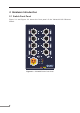
2. Hardware Introduction
2.1 Switch Front Panel
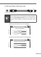
Figure 2-1 and Figure 2-2 shows the front panel of the Industrial M12 Ethernet
Switch.
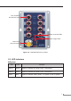
LNK/ACT
PoE-in-Use
LNK/ACT
PoE-in-Use
LNK/ACT
PoE-in-Use
LNK/ACT
PoE-in-Use
1 5
2 6
3 7
4 8
Fault
PWR
2
PWR
1
GND
V2
V2
V1
V1
ISW-808PT-M12
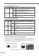
PoE
+
M12
PoE Usage
180W
120W
60W
TX
RX
RX
TX
DC Input:
12-56V
, 6A max.
Figure 2-1: ISW-808PT-M12 Front Panel