Industrial 8-Port 10/100TX M12 802.
Trademarks Copyright © PLANET Technology Corp. 2020 Contents are subject to revision without prior notice. PLANET is a registered trademark of PLANET Technology Corp. The information in this manual is subject to change without notice. All other trademarks belong to their respective owners.
CE Mark Warning This device is compliant with Class A of CISPR 32. In a residential environment this equipment may cause radio interference. Energy Saving Note of the Device This power required device does not support Standby mode operation. For energy saving, please remove the power cable to disconnect the device from the power circuit. Without removing power cable, the device will still consuming power from the power source.
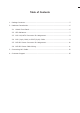
Table of Contents 1. Package Contents........................................................................................ 5 2. Hardware Introduction................................................................................. 6 2.1 Switch Front Panel................................................................................ 6 2.2 LED Indicators..................................................................................... 7 2.3 M12 10/100TX Connector Pin Assignment.......................
1. Package Contents Thank you for purchasing PLANET Industrial M12 802.3at PoE+ Switch. The descriptions of these models are shown below: Model Name ISW-808PT-M12 ISW-808PT-M12A Ethernet Ports Power Connector 8 x 10/100BASE-TX 1 x M23 M12 D-coded 5-pin A-coded Power Input Range DC 12~56V Enclosure IP67 aluminum IP50 metal “Industrial M12 Ethernet Switch” is used as an alternative name in this Quick Installation Guide. Open the box of the Industrial M12 Ethernet Switch and carefully unpack it.
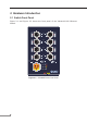
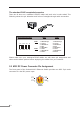
2. Hardware Introduction 2.1 Switch Front Panel Figure 2-1 and Figure 2-2 shows the front panel of the Industrial M12 Ethernet Switch. 1 5 LNK/ACT PoE-in-Use 2 6 LNK/ACT PoE-in-Use 3 7 LNK/ACT PoE-in-Use 4 8 LNK/ACT PoE-in-Use DC Input: 12-56V , 6A max.
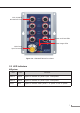
M12 10/100TX 802.3at PoE+ Port Power and Fault LEDs Power Usage LEDs M23 Power Input Connector Figure 2-2: ISW-808PT-M12A Front Panel 2.2 LED Indicators System LED Color Function PWR 1 Green Lights to indicate DC power input 1 has power. PWR 2 Green Lights to indicate DC power input 2 has power. Fault Red Lights to indicate either power 1 or power 2 has no power.
Per 10/100BASE-TX PoE+ Port LED Color LNK/ACT Function Lights To indicate the port is running at 10/100Mbps speed and successfully established. Blinks To indicate the switch is actively sending or receiving data over that port. Lights To indicate the port is providing 45~55 V DC in-line power. Off To indicate the connected device is not a PoE powered device (PD).
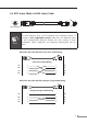
2.4 M12 (4-pin, Male) to RJ45 (8-pin) Cable 1 1 4 2 3 8 M12-4P(M)-D As each Ethernet port of the Industrial M12 Ethernet Switch is running in auto negotiation mode, make sure the Ethernet ports of the corresponding Ethernet devices are also running in auto negotiation mode, otherwise, the Ethernet performance will be poor.
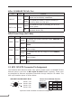
The standard RJ45 receptacle/connector There are 8 wires on a standard UTP/STP cable and each wire is color-coded.
2.6 M23 DC Power Cable Wiring Please use the power cable with the M23 5-pin female connector from the Industrial M12 Ethernet Switch package for DC power input. The M23 DC power cable pin assignment is shown below: V2 V1 V2 V1 CB-M23FSF-120 M23 DC power cable pin assignment and wiring code V1 positive (+) pin = white cable V2V2+ V1V1+ V1 negative (-) pin = brown cable V2 positive (+) pin = black cable V2 negative (-) pin = yellow cable 1.
3. Connecting M12 Cable This following pictures show how to install the device. Note Step 1: Turn counterclockwise to remove the waterproof screw nuts of an M12 connector and power input. Step 2: Insert the M12 UTP male connector into the M12 female Ethernet port of the Industrial M12 Ethernet Switch.
Step 3: Turn clockwise to tighten the screw nut of the M12 connector and make sure the connection is tight. Step 4: Insert the M23 power female connector into the M23 male port of the power input.
Note The box doesn’t include the M23 5-pin A-coded female connector power cable. Step 5: Turn clockwise to tighten the screw nut of the M12 power connector. Step 6: Please refer to chapter 2.2 for LED indicators. Note Before connecting the DC power cord, please check whether your local DC power source is stable. Make sure to tightly close all interfaces to have waterproof effect.
4. Customer Support Thank you for purchasing PLANET products. You can browse our online FAQ resource and User’s Manual on PLANET Web site first to check if it could solve your issue. If you need more support information, please contact PLANET switch support team. PLANET online FAQs: http://www.planet.com.tw/en/support/faq Switch support team mail address: support@planet.com.tw Copyright © PLANET Technology Corp. 2020 Contents are subject to revision without prior notice.