Industrial IP67 Rated 8-Port 10/100Mbps M12 Ethernet Switch ISW-800T-M12 & ISW-804PT-M12 User’s Manual
Trademarks Copyright © PLANET Technology Corp. 2011. Contents subject to revision without prior notice. PLANET is a registered trademark of PLANET Technology Corp. All other trademarks belong to their respective owners. Disclaimer PLANET Technology does not warrant that the hardware will work properly in all environments and applications, and makes no warranty and representation, either implied or expressed, with respect to the quality, performance, merchantability, or fitness for a particular purpose.
CE Mark Warning This is a Class A product. In a domestic environment, this product may cause radio interference, in which case the user may be required to take adequate measures. WEEE Warning To avoid the potential effects on the environment and human health as a result of the presence of hazardous substances in electrical and electronic equipment, end users of electrical and electronic equipment should understand the meaning of the crossed-out wheeled bin symbol.
Table of Contents 1. Introduction................................................................................................ 5 1.1 Package Contents................................................................................. 5 1.2 How to Use This Manual....................................................................... 5 1.3 Product Features.................................................................................. 6 1.4 Product Specifications.............................................
1. Introduction 1.1 Package Contents Check the contents of your package for following parts: ll Industrial IP67 Rated M12 Ethernet Switch x 1 ll User's Manual x 1 ll 1.2m M12-to-RJ45 UTP Cable x 1 ll 1.
1.3 Product Features Physical Port ll 8-Port 10/100Mbps M12 Connector with IP67 protection ll 4-Port IEEE 802.3af PoE Ports (ISW-804PT-M12) (Port 5 to port 8) Layer 2 Features ll Supports Auto-negotiation and 10/100Mbps half / full duplex mode ll High performance Store and Forward architecture, runt/CRC filtering eliminates erroneous packets to optimize the network bandwidth ll Prevents packet loss with back pressure (Half-Duplex) and IEEE 802.
1.
Model ISW-804PT-M12 Hardware Specification 10/100Base-TX Ports 8 x M12, 4-Pin D-coded female connector IEEE 802.
Power over Ethernet PoE Standard IEEE 802.3af Power over Ethernet / PSE PoE Power Supply Type End-Span PoE Power Output 48V DC Per Port, 350mA. Max. 15.
1.
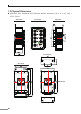
ISW-804PT-M12 Industrial M12 Ethernet Switch dimension (W x D x H): 163 x 103 x 53mm Side View Front View Side View Mounting Kit Rear View DIN-Rail Kit Mounting Kit 11
2. Installation This section describes the functionalities of the Industrial M12 Ethernet Switch’s components and guides how to install it on the desktop. Basic knowledge of networking is assumed. Please read this chapter completely before continuing. 2.
2.1.1 Product Overview The PLANET Industrial M12 Ethernet Switch with 8 RJ-45 10/100Mbps ports M12 interfaces, for high-speed network connectivity. The Industrial M12 Ethernet Switch can also automatically identify and determine the correct transmission speed and half / full duplex mode of the attached devices with its 8 Fast Ethernet ports.
2.1.3 LED Indicators ISW-800T-M12 LED Color Function PWR 1 Green Lit: indicate the power 1 has power. PWR 2 Green Lit: indicate the power 2 has power. FAULT Green Lit: indicate the either power 1 or power 2 has no power. Green Lit: indicate the Switch is successfully connecting to the network at 10/100Mbps. Blink: indicate that the Switch is actively sending or receiving data over that port. Off: indicate the Switch is not connecting to the network at 10/100Mbps.
Please follow the steps below for DC power cable installation on Industrial M12 Ethernet Switch. 1. Plug the DC power cord connector to the power input port of the Industrial M12 Ethernet Switch. 2. Screw the nut on DC power cord female connector to the DC power input male connector of Industrial M12 Ethernet Switch and make sure the connection is tight. Before DC power cord connection, please check and assure your local DC power source is stable. Note 2.1.
2.2 Mounting Installation This section describes how to install the Industrial M12 Ethernet Switch and make connections to it. Please read the following topics and perform the procedures in the order being presented. 2.2.1 DIN-Rail Mounting The DIN-Rail is screwed on the Industrial M12 Ethernet Switch when out of factory.
Step 4: Please refer to following procedures to remove the Industrial M12 Ethernet Switch from the track. Step 5: Lightly press the button of DIN-Rail for remove it from the track. 2.2.2 Wall Mount Plate Mounting To install the Industrial M12 Ethernet Switch on the wall, please follows the instructions described below. Step 1: Remove the DIN-Rail from the Industrial M12 Ethernet Switch; loose the screws to remove the DIN-Rail.
3. Applicaiton In this paragraph, we will describe how to install Industrial M12 Ethernet Switch and the installation points for the attention.
Railway Transmission System Passenger Information System PoE IP Camera Next Stop Entertainment System PoE PoE Laptop N N AP Content Server ISW-804PT-M12 PoE ISW-800T-M12 Control Center ISW-804PT-M12 ISW-800T-M12 PoE IP Camera PoE IP Camera PoE PoE Industrial Backbone Switch PC VoIP PC AP 100Base-TX UTP PoE 100Base-TX UTP with PoE Installation Steps Step 1: Unpack the Industrial M12 Ethernet Switch. Step 2: Check the DIN-Rail is screwed on the Industrial M12 Ethernet Switch.
Step 5: Prepare the twisted-pair, straight through Category 3, 4, 5, 5e, 6 cables for Ethernet connection. Step 6: Insert one side of Category 3, 4, 5, 5e, 6 cables into the Industrial M12 Ethernet Switch Ethernet port (RJ-45 port) and another side of Category 3, 4, 5, 5e, 6 cables to the network devices' Ethernet port (RJ-45 port), ex: switch, PC or Server. The UTP port (RJ-45) LED on the Industrial M12 Ethernet Switch will light up when the cable connected with the network device.
Power over Ethernet Powered Device 3~5 Watts 6~12 Watts 10~12 Watts 3~12 Watts Voice over IP phones Enterprise can install POE VoIP Phone, ATA and other Ethernet/non-Ethernet end-devices to the central where UPS is installed for un-interrupt power system and power control system. Wireless LAN Access Points Museum, Sightseeing, Airport, Hotel, Campus, Factory, Warehouse can install the Access Point any where with no hesitation.
4. Power Over Ethernet Overview What is PoE? Based on the global standard IEEE 802.3af, PoE is a technology for wired Ethernet, the most widely installed local area network technology adopted today. PoE allows the electrical power necessary for the operation of each end-device to be carried by data cables rather than by separate power cords. New network applications, such as IP Cameras, VoIP Phones, and Wireless Networking, can help enterprises improve productivity.
POWER SOURCING EQUIPMENT (PSE) POWERED DEVICE (PD) 4 4 5 + 48V - 1 TX 2 3 RX 5 SPARE PAIR 1 2 SIGNAL PAIR 6 RX DC / DC 3 6 Converter Converter TX SIGNAL PAIR 7 7 8 8 SPARE PAIR Figure 1 - Power Supplied over the Spare Pins The data pairs are used. Since Ethernet pairs are transformer coupled at each end, it is possible to apply DC power to the center tap of the isolation transformer without upsetting the data transfer.
When to install PoE? Consider the following scenarios: ll You’re planning to install the latest VoIP Phone system to minimize cabling building costs when your company moves into new offices next month. ll The company staff has been clamoring for a wireless access point in the picnic area behind the building so they can work on their laptops through lunch, but the cost of electrical power to the outside is not affordable.
5. Troubleshooting This chapter contains information to help you solve issues. If the Industrial M12 Ethernet Switch is not functioning properly, make sure the Industrial M12 Ethernet Switch was set up according to instructions in this manual. The per port LED is not lit Solution: Check the cable connection of the Industrial M12 Ethernet Switch. Performance is bad Solution: Check the speed duplex mode of the partner device.
Appendix A: Networking Connection A.1 Switch’s RJ-45 Pin Assignments 10/100Mbps, 10/100Base-TX RJ-45 Connector pin assignment Contact MDI Media Dependant Interface MDI-X Media Dependant Interface -Cross 1 Tx + (transmit) Rx + (receive) 2 Tx - (transmit) Rx - (receive) 3 Rx + (receive) Tx + (transmit) 4, 5 Not used 6 Rx - (receive) 7, 8 Tx - (transmit) Not used A.
The standard RJ-45 receptacle/connector There are 8 wires on a standard UTP/STP cable and each wire is color-coded.
This page is intentionally left blank