
User Manual


7
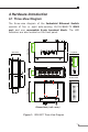
4. Hardware Introduction
4.1 Three-View Diagram
The three-view diagram of the Industrial Ethernet Switch
consists of ve or eight auto-sensing 10/100/BASE-TX RJ45
port and one removable 6-pin terminal block. The LED
indicators are also located on the front panel.
18.00
9.00
91.00
52.00
52.00
104.00
30.00
50.00
30.00
70.00
21.69
28.65
Dimensions ( unit = mm )
Side View Front View Side View
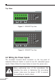
Top View
Bottom View
Rear View
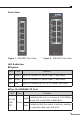
P1 P2 FAULT
ACT
LNK
10/100
1
2
3
4
5
ISW-500T
Input
DC12~48V, AC 24V
V1+ 1A@24VV1-
DC1
V2+ V2-
DC2
Fault
Figure 1: ISW-500T Three-View Diagram