Industrial 5-/8-Port 10/100TX Compact Ethernet Switch ISW-500T/ISW-800T User’s Manual
Table of Contents 1. Package Contents.............................................................. 3 2. Product Features............................................................... 4 3. Product Specifications........................................................ 5 4. Hardware Introduction....................................................... 7 4.1 Three-View Diagram.................................................... 7 4.2 Wiring the Power Inputs............................................ 10 4.
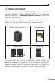
1. Package Contents Thank you for purchasing PLANET industrial 5-/8-port 10/100TX Compact Ethernet Switch, ISW-500T/800T. In the following section, the term “Industrial Ethernet Switch” means the ISW-500T or ISW-800T. Open the box of the Industrial Ethernet Switch and carefully unpack it.
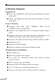
2. Product Features Physical Port 5-port 10/100BASE-TX RJ45 with auto MDI/MDI-X function (ISW-500T) 8-port 10/100BASE-TX RJ45 with auto MDI/MDI-X function (ISW-800T) Layer 2 Features Complies with IEEE 802.3 100BASE-TX Ethernet standard 10BASE-T, IEEE 802.3u Supports auto-negotiation and 10/100Mbps half/full duplex mode Prevents packet loss with back pressure (half-duplex) and IEEE 802.3x pause frame flow control (full-duplex) Complies with IEEE 802.
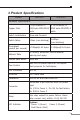
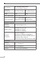
3. Product Specifications Product ISW-500T ISW-800T Hardware Specifications Copper Ports 5 10/100BASE-TX 8 10/100BASE-TX RJ45 auto-MDI/MDI-X RJ45 auto-MDI/MDI-X ports ports Switch Architecture Store-and-Forward Switch Fabric 1Gbps (non-blocking) 1.6Gbps (non-blocking) Throughput (packet per second) 0.74Mpps@ 64 bytes 1.19Mpps@ 64 bytes Address Table 1K entries, automatic source address learning and aging Shared Data Buffer 448K bits Flow Control IEEE 802.
LED Indicator Per 10/100TX RJ45 Ports: 10/100 LNK/ACT (Green) Dimensions (W x D x H) 70 x 104 x 30 mm 70 x 115 x 41 mm Weight 255g 300g Power Requirements Dual 12~48V DC, 24V AC Power Consumption Max. 2.5 Max. 2 watts/6.86BTU watts/8.
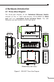
4. Hardware Introduction 4.1 Three-View Diagram The three-view diagram of the Industrial Ethernet Switch consists of five or eight auto-sensing 10/100/BASE-TX RJ45 port and one removable 6-pin terminal block. The LED indicators are also located on the front panel. 21.69 Side View 28.65 Rear View 70.00 Top View DC1 Fault DC2 ISW-500T 5 4 3 2 1 ACT P2 FAULT Input DC12~48V, AC 24V P1 10/100 LNK 1A@24V V2+ V2- 91.00 9.00 Front View V1+ V1- 52.00 104.00 30.00 Bottom View 52.00 18.
27.19 Side View 28.65 Rear View 70.00 Top View DC1 Fault DC2 8 7 6 5 4 3 2 ISW-800T 41.00 10/100 LNK ACT P2 FAULT P1 Input DC12~48V, AC 24V 103.00 1 1A@24V V2+ V2- 5.50 Front View V1+ V1- 115.00 3.50 Bottom View 18.00 Side View 30.00 50.
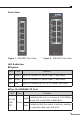
Front View P1 P1 10/100 LNK P2 FAULT P2 FAULT ACT 1 1 2 3 2 4 5 3 6 7 4 8 10/100 LNK ACT 5 ISW-800T ISW-500T Figure 1: ISW-500T Front View Figure 2: ISW-800T Front View LED Definition: System LED Color Function DC1 Green Lights to indicate DC power input 1 has power. DC2 Green Lights to indicate DC power input 2 has power. Fault Red Lights to indicate that AC or DC power has failed.
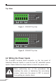
Top View 1 2 3 4 5 6 V1+ V1- 1A@24V V2+ V2Fault DC1 DC2 Input DC12~48V, AC 24V Figure 1: ISW-500T Top View 1 2 3 4 5 6 V1+ V1DC1 1A@24V V2+ V2Fault DC2 Input DC12~48V, AC 24V Figure 2: ISW-800T Top View 4.2 Wiring the Power Inputs The 6-contact terminal block connector on the top panel of Industrial Ethernet Switch is used for two DC redundant power inputs. Please follow the steps below to insert the power wire.
1. Insert positive and negative DC power wires into contacts 1 and 2 for POWER 1, or contacts 5 and 6 for POWER 2. 1 2 3 4 5 6 V1+ V1DC1 1A@24V V2+ V2Fault DC2 Input DC12~48V, AC 24V 2. Tighten the wire-clamp screws for preventing the wires from loosening. 1 2 3 4 5 6 Power 1 Fault Power 2 + - + - 1. The wire gauge for the terminal block should be in the range between 12 and 24 AWG. Note 2.
4.3 Wiring the Fault Alarm Contact The fault alarm contacts are in the middle of the terminal block connector as the picture shows below. Inserting the wires, the Industrial Ethernet Switch will detect the fault status of the power failure and then forms an open circuit.
5. Installation This section describes the functionalities of the Industrial Ethernet Switch’s components and guides you to installing it on the DIN rail and wall. Please read this chapter completely before continuing. Note This following picture tells the user how to install the device, and the device is not ISW-500T or ISW-800T. 5.1 DIN-rail Mounting Installation The DIN rail is screwed on the Industrial Ethernet Switch when out of factory.
Step 2: Lightly insert the bottom of the switch into the track. 1 2 Step 3: Make sure the DIN rail is tightly secured on the track. Step 4: Please refer to the following procedure to remove the Industrial Ethernet Switch from the track.
Step 5: Lightly pull out the bottom of the switch for removing it from the track. 5.2 Wall-mount Plate Mounting To install the Industrial Ethernet Switch on the wall, please follow the instructions described below. Step 1: To remove the DIN rail from the Industrial Ethernet Switch, loosen the screws. Step 2: Place the wall-mount plate on the rear panel of the Industrial Ethernet Switch. Step 3: Use the screws to screw the wall-mount plate on the Industrial Ethernet Switch.
Customer Support Thank you for purchasing PLANET products. You can browse our online FAQ resource on PLANET web site first to check if it could solve your issue. If you need more support information, please contact PLANET switch support team. PLANET online FAQ : http://www.planet.com.tw/en/support/faq.php Switch support team mail address : support_switch@planet.com.tw Copyright © PLANET Technology Corp. 2017. Contents are subject to revision without prior notice.