4-Port 10/100Mbps +1/2 100FX Fiber Port Industrial Fast Ethernet Switch ISW-511 / ISW-621 Series ISW-511T / ISW-621T Series User's Manual
Trademarks Copyright © PLANET Technology Corp. 2011 Contents subject revision without prior notice PLANET is a registered trademark of PLANET Technology Corp. other trademarks belong to their respective owners. All Disclaimer PLANET Technology does not warrant that the hardware will work properly in all environments and applications, and makes no warranty and representation, either implied or expressed, with respect to the quality, performance, merchantability, or fitness for a particular purpose.
FCC Warning This equipment has been tested and found to comply with the limits for a Class A digital device, pursuant to Part 15 of the FCC Rules. These limits are designed to provide reasonable protection against harmful interference when the equipment is operated in a commercial environment. This equipment generates, uses, and can radiate radio frequency energy and, if not installed and used in accordance with the Instruction manual, may cause harmful interference to radio communications.
Table of Contents 1. Introduction............................................................................... 6 1.1 Package Contents................................................................. 6 1.2 How to Use This Manual........................................................ 6 1.3 Product Features.................................................................. 7 1.4 Product Specifications........................................................... 8 2. Installation................................
4.5 Auto-negotiation..................................................................28 5 Troubleshooting.........................................................................29 APPENDIX A: Networking Connection................................................30 A.1 Switch’s RJ-45 Pin Assignments............................................30 A.2 RJ-45 cable Pin Assignments................................................
1. Introduction 1.1 Package Contents Check the contents of your package for following parts: ● Industrial Fast Ethernet Switch x 1 ● User's Manual x 1 ● DIN Rail Kit x 1 ● Wall Mount Kit x 1 If any of these are missing or damaged, please contact your dealer immediately, if possible, retain the carton including the original packing material, and use them against to repack the product in case there is a need to return it to us for repair. 1.
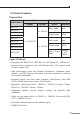
1.3 Product Features Physical Port Ports Model Name Copper Fiber Optical Interface Optical Mode ISW-511 ISW-511T Mutil-mode 2km Single-mode 15km Multi-mode 2km Single-mode 15km 1 x 100-FX ISW-511S15 ISW-511TS15 ISW-621 ISW-621T Distance 4 x 10/100-TX ISW-621S15 2 x 100-FX ISW-621TS15 Depend Multi / Single on SFP Mode Module ISW-621TF Layer 2 Features □ Complies with IEEE 802.3, IEEE 802.
Industrial Case / Installation □ IP-30 Metal case / Protection □ DIN Rail and Wall Mount Design □ 12 to 48V DC, redundant power with polarity reverse protect function and connective removable terminal block for master and slave power □ -10 to 60 Degree C operation temperature on ISW-511 / ISW511S15 / ISW-621 / ISW-621S15 □ -40 to 75 Degree C operation temperature on ISW-511T / ISW511TS15 / ISW-621T / ISW-621TS15 / ISW-621TF 1.
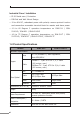
Switch Specification Switch Processing Scheme Store-and-Forward Address Table 2K entries Buffer 1Mbit Flow Control Back pressure for Half duplex, IEEE 802.3x Pause Frame for Full duplex Switch Fabric 1Gbps Throughput (Packet Per Second) 0.74Mpps @ 64Bytes Standards Conformance Standards Compliance IEEE 802.3 Ethernet, 10Base-T IEEE 802.3u Fast Ethernet, 100Base-TX, 100Base-FX IEEE 802.
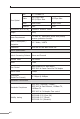
Fiber Optical Port 1 x 100Base-FX Cable 50/125μm fiber 62.5/125μm fiber 9/125μm fiber Mode Multi-mode Single-mode Distance 2km 15km Dimensions (W x D x H) 135mm x 97mm x 32mm Weight 436g Power Requirement 12~48V DC, Redundant power with polarity reverse protection function Power Consumption / Dissipation 13.
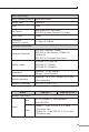
Temperature Operating: -40~75 Degree C Storage: -40~85 Degree C Humidity Operating Operating: 5% to 90%, Storage: 5% to 90% (Non-condensing) Regulation Compliance FCC Part 15 Class A, CE Model ISW-621 ISW-621S15 Hardware Specification Ports 4 x 10/100Base-TX, Auto-negotiation, Auto-MDI/ MDI-X Cable 10Base-T : 2-pair UTP Cat. 3, 4, 5 cable (100meters, max.) 100Base-TX : 2-pair UTP Cat. 5, 5e, 6 cable (100meters, max.) Port 2 x 100Base-FX Cable 50/125μm fiber 62.
Flow Control Back pressure for Half duplex, IEEE 802.3x Pause Frame for Full duplex Switch Fabric 1.2Gbps Throughput (Packet Per Second) 0.89Mpps @ 64Bytes Standards Conformance Standards Compliance IEEE 802.3 Ethernet, 10Base-T IEEE 802.3u Fast Ethernet, 100Base-TX, 100Base-FX IEEE 802.
Dimensions (W x D x H) 135mm x 97mm x 32mm Weight 442g Power Requirement 12~48V DC, Redundant power with polarity reverse protection function Power Consumption / Dissipation 16 Watts / 54BTU Installation DIN Rail Kit and Wall Mount Ear Switch Specification Switch Processing Scheme Store-and-Forward Address Table 2K entries Buffer 1Mbit Flow Control Back pressure for Half duplex, IEEE 802.3x Pause Frame for Full duplex Switch Fabric 1.2Gbps Throughput (Packet Per Second) 0.
2. Installation This section describes the functionalities of the Industrial Fast Ethernet Switch’s components and guides how to install it on the desktop. Basic knowledge of networking is assumed. Please read this chapter completely before continuing. In the following section, the term “Industrial Fast Ethernet Switch” means the ISW-511 / ISW-621 series and ISW-511T / ISW-621T series 2.
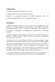
2.1.1 Switch Front Panel Figure 2-1 & 2-2 & 2-3 & 2-4 shows a front panel of Industrial Fast Ethernet Switch.
Figure 2-3 ISW-511T / ISW-511TS15 front panel 16 Figure 2-4 ISW-621T / ISW-621TS15 front panel Figure 2-5 ISW-621TF front panel
2.1.2 LED Indicators LED Color Function P1 Green Lit: indicate the power 1 has power. P2 Green Lit: indicate the power 2 has power. FAULT Green Lit: indicate the either power 1 or power 2 has no power. 100 Green Fiber Optical Lit: indicate the Fiber port is successfully connecting to the network at 100Mbps. Copper Lit: indicate the Switch is successfully connecting to the network at 100Mbps. Off: indicate that the Switch is successfully connecting to the network at 10Mbps.
2.1.4 Wiring the Power Inputs The 6-contact terminal block connector on the top panel of Industrial Fast Ethernet Switch is used for two DC redundant powers input. Please follow the steps below to insert the power wire. 1. Insert positive / negative DC power wires into the contacts 1 and 2 for POWER 1, or 5 and 6 for POWER 2. V1- V1 + V2 - V2 + 2. Tighten the wire-clamp screws for preventing the wires from loosing.
2.1.5 Wiring the Fault Alarm Contact The fault alarm contacts are in the middle of the terminal block connector as the picture shows below. Inserting the wires, the Industrial Fast Ethernet Switch will detect the fault status of the power failure, or port link failure (available for managed model) and then forms an open circuit. The following illustration shows an application example for wiring the fault alarm contacts. 1 2 3 4 5 6 Insert the wires into the fault alarm contacts Note 1.
2.2 Mounting Installation This section describes how to install the Industrial Fast Ethernet Switch and make connections to it. Please read the following topics and perform the procedures in the order being presented. Note In the installation steps below, this Manual use IGS-801 (PLANET 8 Port Industrial Gigabit Switch) as the example. However, the steps for PLANET Industrial Switch & Industrial Media Converter are similar. 2.2.
Step 2: Lightly press the button of DIN-Rail into the track. 1 2 Step 3: Check the DIN-Rail is tightly on the track. Step 4: Please refer to following procedures to remove the Industrial Fast Ethernet Switch from the track.
Step 5: Lightly press the button of DIN-Rail for remove it from the track. 2 1 2.2.2 Wall Mount Plate Mounting To install the Industrial Fast Ethernet Switch on the wall, please follows the instructions described below. Step 1: Remove the DIN-Rail from the Industrial Fast Ethernet Switch; loose the screws to remove the DIN-Rail. Step 2: Place the wall mount plate on the rear panel of the Industrial Fast Ethernet Switch.
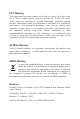
3. Application In this paragraph, we will describe how to install Industrial Fast Ethernet Switch and the installation points for the attention.
Weather Station IP Camera ISW-511TS15 Desert IP Camera ISW-511TS15 15km 100 100 15km IP Camera IP Camera Fiber Switch 15km 100 Data Center 15km ISW-511TS15 100 IP Camera 15km ISW-511TS15 100 ISW-511TS15 ISW-511T Steel Factory Winter season of Country 100Base-FX Fiber-optic 100 100Base-TX UTP Weather Station IP Camera Desert IP Camera IP Camera IP Camera 15km 100 ISW-621TS15 ISW-621TS15 15km 100 15km Fiber Switch 100 100 15km 15km 100 Data Center 15km 100 ISW-621TS15
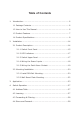
Weather Station IP Camera Desert IP Camera IP Camera IP Camera 20km (Single mode) 100 ISW-621TF ISW-621TF 100 2km (Multi-mode) 20km (Single mode) Fiber Switch 100 40km (Single mode) 100 60km (Single mode) Data Center 2km (Multi-mode) 100 100 ISW-621TF IP Camera IP Camera 2km (Multi-mode) 2km (Multi-mode) 100 ISW-621TF Winter season of Country 100 ISW-621TF Steel Factory 100 ISW-621TF 100Base-FX Fiber-optic 100Base-TX UTP 25
Installation Steps Step 1: Unpack the Industrial Fast Ethernet Switch. Step 2: Check the DIN-Rail is screwed on the Industrial Fast Ethernet Switch. (Please refer to DIN-Rail Mounting section for DIN-Rail installation. If you want to wall mount the Industrial Fast Ethernet Switch, then please refer to Wall Mount Plate Mounting section for wall mount plate installation. Step 3: To hang the Industrial Fast Ethernet Switch on the DIN-Rail track or wall, please refer to the Mounting Installation section.
4. Switch Operation 4.1 Address Table The Industrial Fast Ethernet Switch is implemented with an address table. This address table composed of many entries. Each entry is used to store the address information of some node in network, including MAC address, Port No. and etc. This information comes from the learning process of Industrial Fast Ethernet Switch. 4.
4.4 Store-and-Forward Store-and-Forward is one type of packet-forwarding techniques. A Store-and-Forward Industrial Switch stores the incoming frames in an internal buffer and checks any error from the frames before transmission. No error packets occurrence, it is the best choice when a network needs efficiency and stability.
5. Troubleshooting This chapter contains information to help you solve issues. If the Industrial Fast Ethernet Switch is not functioning properly, make sure the Industrial Fast Ethernet Switch was set up according to instructions in this manual. The Link LED is not light Solution: Check the cable connection of the Industrial Fast Ethernet Switch. Performance is bad Solution: Check the speed duplex mode of the partner device.
APPENDIX A: Networking Connection A.
A.2 RJ-45 cable Pin Assignments The standard RJ-45 receptacle/connector There are 8 wires on a standard UTP/STP cable and each wire is colorcoded.
EC Declaration of Conformity For the following equipment: *Type of Product *Model Number : 4+1 / 4+2 100FX Port Industrial Ethernet Switch : ISW-511 / ISW-511S15 / ISW-511T / ISW-511TS15 ISW-621 / ISW-621S15 / ISW-621T / ISW-621TS15 / ISW-621TF * Produced by: Manufacturer‘s Name : Planet Technology Corp. Manufacturer‘s Address : 10F., No.96, Minquan Rd., Xindian Dist., New Taipei City 231, Taiwan (R.O.C.