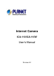
Internet Camera ICA-110/ICA-110W User’s Manual Version 1.
Copyright Copyright (C) 2005 PLANET Technology Corp. All rights reserved. The products and programs described in this User’s Manual are licensed products of PLANET Technology, This User’s Manual contains proprietary information protected by copyright, and this User’s Manual and all accompanying hardware, software, and documentation are copyrighted.
and electronic equipment should understand the meaning of the crossedout wheeled bin symbol. Do not dispose of WEEE as unsorted municipal waste and have to collect such WEEE separately. Trademarks The PLANET logo is a trademark of PLANET Technology. This documentation may refer to numerous hardware and software products by their trade names. In most, if not all cases, their respective companies claim these designations as trademarks or registered trademarks.
TABLE OF C ONTENTS ABOUT THIS GUIDE ...................................................6 INTRODUCTION ............................................................7 FEATURES AND BENEFITS ..................................................8 UNPACKING THE PACKAGE ..............................................10 SYSTEM REQUIREMENT ...................................................11 PHYSICAL DESCRIPTION ..................................................12 HARDWARE INSTALLATION ................................
INSTALLATION .................................................................54 GETTING STARTED...........................................................59 USING IPVIEW PRO .........................................................62 CONFIGURING THE SYSTEM .............................................67 APPENDIX .....................................................................82 A FREQUENTLY ASKED QUESTIONS ................................82 B PING YOUR IP ADDRESS ......................................
A BOUT T HIS G UIDE This manual provides instructions and illustrations on how to use your Internet Camera, includes: z Chapter 1, Introduction, provides the general information on the camera. z Chapter 2, Hardware Installation, describes the hardware installation procedure for the camera. z Chapter 3, Security, explains the security feature of the camera. z Chapter 4, Application of the Camera, provides the illustrations of the camera’s applications.
1 I NTRODUCTION Thank you for purchasing the ICA-110W/ICA-110 Wireless/ Internet Camera, a camera device that can be connected directly to an Ethernet or Fast Ethernet network and also supported by the wireless transmission based on the IEEE 802.11g standard. Compared to the conventional PC Camera, the ICA-110/ICA110W features a built-in CPU and web-based solutions that can provide a cost-effective solution to transmit real-time high-quality video images and sounds for monitoring.
Features and Benefits Simple To Use The ICA-110/ICA-110W is a standalone system with built-in CPU requiring no special hardware or software such as PC frame grabber cards. The ICA-110/ICA-110W supports both ActiveX mode (for Internet Explorer users) and Java mode (for Internet Explorer and Netscape Navigator users). Therefore, all that is required is a web browser software such as Internet Explorer 5.0 or above or Netscape 6.0 or above.
RS-485 Support The pin 5 & 6 of the I/O connectors are used for RS-485 data transmission. You can connect a special featured device (such as an external camera stand with rotation function) to meet your needs. When the external device is connected, you could configure the settings and control the device from the RS485 window of Web Configuration Utility.
Unpacking the Package Unpack the package and check all the items carefully. In addition to this User’s manual, be certain that you have: One ICA-110 or ICA-110W (with external antenna) One Installation CD-ROM One Quick Installation Guide One AC power adapter suitable for your country’s electric power One Camera Stand One RJ-45 Ethernet Cable If any item contained is damaged or missing, please contact your local dealer immediately.
System Requirement Networking Local Area Network: 10Base-T Ethernet or 100Base-TX Fast Ethernet. Wireless Local Area Network: IEEE 802.11g Wireless LAN. Accessing the Camera For Web Browser Users Operating System: Microsoft® Windows® 98SE/ME/ 2000/XP CPU: Intel Celeron 1.1GHz or above (Intel Pentium 4 is preferred) Memory Size: 128MB or above Resolution: 800x600 or above Microsoft® Internet Explorer 5.
Physical Description This section describes the externally visible features of the ICA110/ICA-110W. Front Panel 2. Power LED 1. Link LED 3. Internal MIC 1. Link LED The Link LED is positioned on the right side of the ICA110/ICA-110W’s lens while facing the ICA-110/ICA-110W. It is located to the left of the Power LED. A steady ORANGE light confirms that the camera has good connection to LAN connectivity.
2. Power LED The Power LED is positioned on the right side of the ICA110/ICA-110W’s lens while facing the ICA-110/ICA-110W. A steady BLUE light confirms that the ICA-110/ICA-110W is powered on. 3. Internal MIC The built-in omni-directional microphone allows the camera to receive sound and voice.
Figure 1-3: Rear panel of ICA-110W 1. External Antenna The rotatable external antenna allows you to adjust its position to obtain the maximum signal. 2. Network Cable Connector The ICA-110/ICA-110W’s rear panel features an RJ-45 connector for connections to 10Base-T Ethernet cabling or 100Base-TX Fast Ethernet cabling (which should be Category 5 twisted-pair cable).
light up. Release the reset button and the Power LED will begin to flash, indicating the ICA-110/ICA-110W is changing to factory reset. When factory reset is completed, the SSID is set as “NULL String” (This default setting will let the ICA-110W connect to ANY access point on the infrastructure network). The IP address will also return to the default setting as 192.168.0.20. 4.
Screw Hole Bottom Panel Screw Hole 16
Screw Hole Located on the top/bottom panel of the camera, the screw hole is used to connect the camera stand onto the camera by attaching the screw head on the camera stand into the screw hole of the camera.
2 H ARDWARE I NSTALLATION Attaching the Camera to the Stand The ICA-110/ICA-110W comes with a camera stand (optional) with a swivel ball screw head that can be attached to the ICA110/ICA-110W's bottom screw hole. Attach the camera stand to the ICA-110/ICA-110W and station it for your application. There are three holes located in the base of the camera stand allowing the ICA-110/ICA110W to be mounted on the ceiling or any wall securely.
Connecting the Ethernet cable Connect an Ethernet cable to the network cable connector located on the ICA-110/ICA110W’s rear panel, and then attach it to the network. Attaching the Power Supply Attach the external power supply to the DC power input connector located on ICA110/ICA-110W’s rear panel, and then connect it to your local power supply. TIP: You can confirm power source is supplied from the LED indicators label Power on the ICA-110/ICA-110W is illuminated.
3 S ECURITY To ensure the highest security and prevent unauthorized usage of the ICA-110/ICA-110W the Administrator has the exclusive privilege to access the System Administration for settings and control requirements to allow users the level of entry and authorize the privileges for all users.
4 A PPLICATION O F T HE C AMERA The ICA-110/ICA-110W can be applied in wide variety of applications. With the built-in CPU, it can work as a standalone system that provides a web-based solution transmitting high quality video images and sounds for monitoring purposes. It can be managed remotely, accessed and controlled from any PC desktop over the Intranet or Internet via a web browser. With the easy installation procedure, real-time live images will be available.
Applications z Monitoring of local and remote places and objects such as construction sites, hospitals, amusement parks, schools and day-care centers through the use of a web browser. z Capture single frame images from the IPView Pro application. z Configure the camera to upload image or send email messages with a single frame image.
Application Diagrams of the Camera Home Applications 23
Office Applications 24
5 U SING THE C AMERA You can access and manage the ICA-110/ICA-110W through: 1) a web browser, and 2) the enclosed software IPView Pro. This chapter describes the Web Configuration Utility, and provides the instructions on using the camera with a web browser. Web Configuration Utility The ICA-110/ICA-110W must be configured through its built-in Web-based Configuration. (Extensive knowledge of LAN will be helpful in setting up the ICA-110/ICA-110W.) From the web browser, enter the default IP address 192.
Default IP address Pre-view area Welcome Screen of the Configuration Utility After the default IP address is entered from the browser, the Internet Camera Welcome screen will appear with a still image.
System Administration The Configuration Utility contains ten options in the top menu bar, including: System, Date/Time, Video/Audio, Network, Users, Trigger, Upload, RS-485, Information, Tools, and Home. TIP: Once you have changed the settings in each option, click Save to store the settings, or Cancel to abandon, or Refresh to reload the status. During the configuration, whenever you click Home in the top menu bar will make you return to the Welcome window.
Location This field is used for entering a descriptive name for the location used by the camera. Date/Time The Date/Time window contains commands to set up the camera's time and date, providing correct information to the remote users who might be thousands of miles away from the camera’s location. Date & Time - Server’s Time: Display the current date/time settings of the camera.
- - - TimeZone: Select the time zone for the region from the pulldown menu. (Please refer to the Appendix for the time zone selection table.) Synchronized with Time Server: Select this option and the time will be based on GMT setting. When selecting the option, you have to enter the required information in the following fields: • IP Address - Enter the IP Address of the Time Server in this field. • Protocol – Select proper protocol: NTP or TIME.
Environment Select Outdoor or Indoor according to the installation location of the camera. Light Frequency Select 60HZ or 50HZ. Video Resolution Select the desired video resolution from three formats: 176x144, 320x240, and 640x480. The higher setting can obtain better quality; however, it will use more resource within your network.
Compression Rate Select the desired compression rate from five levels: Lowest, Low, Medium, High, and Highest. The higher compression rate can increase the data transmission over the network; however, it will provide poorer image quality. Frame Rate Select the optimal setting depending on your network status. Please note that the higher setting can obtain better quality; however, it will use more resource within your network. The available settings are 1, 3, 7, 12, 15, 25 and 30(Frame/Sec).
- Brightness: Adjust the brightness level ranging from -64 to +64. Saturation: Adjust the colors level ranging from -64 to +64. Contrast: Adjust the contrast level ranging from -64 to +64. Sharpness: Adjust the sharpness level ranging from -6 to +6. Network The Network window contains commands that allow you to set up networking configuration of the camera.
IP Assignment - - - Use Static IP Address: You can select this option and enter the IP address directly. The default settings are: • IP Address – 192.168.0.20 • Subnet Mask – 255.255.255.0 • Default Gateway – 0.0.0.0 Obtain IP address automatically via DHCP: If your network uses the DHCP server, select this option. According to this setting, the camera will be assigned an IP address from the DHCP server automatically.
Wireless Interface - - - - Connection Mode: Use this option to determine the type of wireless communication for the camera. The available settings are Infrastructure mode and Adhoc mode. ESSID: The ESSID (Extended Service Set ID) is a unique identifier shared among all points in a wireless network environment. The default Network Name is blank space (NULL String), and this default setting will allow the camera to connect to ANY access point under the infrastructure network mode.
- WEP Key: To enable WEP Encryption, you should decide the encryption format first by selecting the ASCII or HEX, and then input the WEP key. ASCII input format: ASCII format causes each character you type to be interpreted as an eight-bit value. All unaccented upper- and lower-case Western European characters that can be input through your keyboard's typing zone are valid. To setup a 64-bit WEP key, input 5 ASCII characters. For example, ‘12345’. To setup an 128-bit WEP key, input 13 ASCII characters.
Users The Users window contains commands that allow the system administrator to assign legal users who are permitted to monitor the camera from the remote site. Administrator This field is used for entering the administrator password to access the settings. Enter the password in the Admin Password box, and then enter the same one again in the Confirm Password box to confirm the password. The default setting for Admin is blank space (Null String).
Add User - User Name: Enter the user name in this field (a maximum of 32 characters, printable ASCII code). A maximum of 32 users names are allowed; however, each users name must be different. Each user name can be used as a group given the password. For example, if the User Name is “Guest” and the User Password is “Guest”, anyone can access the camera with these details used as a group of users under the User Name “Guest”.
Trigger The Trigger window contains the control settings for external device through the I/O port, and the settings required for e-mail. - SMTP Server Address: To use the e-mail alert function, you must enter the mail server address in the field. Sender e-mail Address: Enter the e-mail Address of sender. Receiver e-mail Address 1/2: Enter the e-mail Address of receiver(s). User Name: Enter the user name according to SMTP server setting in this field.
- Password: Enter the user password according to SMTP server setting in this field. Sending Interval: Enter the time interval to send next e-mail; the unit is by second. Sending Times: Enter the sending times for every e-mail alert. When completed, you can do a test to confirm the related settings by checking the Send a test e-mail item. Trigger Output Check the item to enable the camera to receive the signal from specified sensor device, and then enter the proper output period in the Time Interval field.
Upload To upload the image to FTP server, you need to configure the related settings in the Upload window. FTP Server This field contains the following five basic settings for your FTP server. - Host Address: The IP Address of the target FTP server. - Port Number: The standard port number for the FTP server is Port 21, and it’s also the default setting. If the FTP server uses a specific port, please confirm the IT manager. - User Name: Enter the user name according to FTP server setting in this field.
- Password: Enter the user password according to FTP server setting in this field to login the FTP server. Directory Path: Enter an existing folder name in this field, and the images will be uploaded to the given folder. Operation To enable the FTP upload function, check the Enable upload video to FTP server option, and then configure the following settings according to your necessary. - Always: Allows you to upload the video to FTP server continuously. - Schedule: Allows you to manage the uploading task.
RS485 The RS485 window contains the control settings for external device through the I/O port. You have to configure the respective settings in this window. Select Enable to enable the function for your camera, and configure the related settings in the following fields. NOTE: When RS485 function is enabled, the system will provide the additional control buttons on the View Image screen (ActiveX mode and Java mode). See the illustrations on page 50.
Port setting Select the proper protocol setting from the two options: Popular protocol command setting or Custom protocol setting. - Popular protocol command setting: Select the proper protocol from the pull-down menu. Click the Preset Position button to bring up a control window, which allows you to control the camera with more options. Arrow buttons • • • Arrow buttons: Use these buttons to move the camera’s lens to your desired position.
- Custom protocol setting: Select this field allows you to configure the commands protocol manually. You can click Test to test each command that you have assigned. In the Name and Command String boxes, you can customize more buttons for your needs. Please note that the setting values in the Command String boxes should be from the connected external device (please refer to the manual of connected external device).
MAC Address This field displays the MAC Address of the camera. IP Address This field displays the IP Address of the camera. Tools The Tools window contains commands for restarting the camera and upgrading firmware. Reboot Do you really want to reboot this device? Click YES from this option, and you can restart the camera just like turning the device off and on and saved settings are retained.
Factory Reset Do you really want to factory reset this device? Click YES from this option, and you can resume all factory default settings for the camera. NOTE: You have to configure the network settings again after a Factory Reset. LED Control The LED control allows user to setup the LED illumination as desired. This feature provides the flexibility when surveillance activity is ON. There are three options: Normal, ON, and OFF. Normal OFF Dummy Power - Steady On of the LED indicator.
Update Firmware This option allows you to update the firmware of the camera once you obtained a latest version of firmware. Click Browse to find the firmware file saved in your computer, and then click Update. NOTE: It will take a few minutes to update firmware. Please wait to complete the procedure; you can then reboot the camera.
Camera Name/Location: The Camera name and location will be displayed when the Camera Name/Location fields are entered in the System configuration page. Video/Audio: You can turn enable/disable the video and audio function by clicking the desired selection. Trigger: you can turn on/off the output device manually by clicking the OFF button. Browse/Capture: Allow you to capture and save the video image. Press the Browe button to select a desired location.
When you enable RS485 function of the camera, the system will provide the additional control buttons on the screen (as show below). You can use the Up, Down, Left, and Right buttons to move the camera’s lens to your desired position. Click the Home button to return to the default home position.
If you select Custom protocol setting in RS485 configuration window (see page43), you can use the Custom Command pulldown menu to select one position, then click Go To to move the camera’s lens to your desired position. NOTE: In the View Image screen (ActiveX mode and Java mode), Preset Position will be unavailable when you select to use Custom Command.
Camera Name/Location: The Camera name and location will be displayed when the Camera Name/Location fields are entered in the Web Configuration Utility. Video/Audio: You can turn enable/disable the video and audio function by clicking the desired selection. Trigger: you can turn on/off the output device manually by clicking the OFF button. Browse/Capture: Allow you to capture and save the video image.
NOTE: 1. Please refer to the appendix on how to install ActiveX, including 1.) install to the Web Server, and 2.) install to your Local PC. 2. The administrator has the authority to set the upload video function through the setting in the Upload option of Configuration Utility. 2. The administrator has the authority to set the e-mail video function through the setting in the Trigger option of Configuration Utility.
6 IPV IEW P RO This chapter describes IPView Pro, which is a powerful software application designed with a user-friendly interface for ease of control and navigation requirements. Installation Step 1 Insert the CD-ROM into the CD-ROM drive to initiate the autorun program. The menu screen will appear as below: Click the IPView Pro item to activate the InstallShield Wizard.
Step 2 Click Next in the welcome screen. Step 3 Read and accept the License Agreement; then, click Yes.
Step 4 Choose the destination location. If no specific requirement, leave the default setting and click Next. Step 5 The InstallShield Wizard starts to install the software, and the progress bar indicates the installation is proceeding.
Step 6 If you use Windows® 2000/XP, it will appear a Digital Signature warning screen. Click Continue Anyway (Windows® XP) or Yes (Windows® 2000). Windows® XP Windows® 2000 Step 7 Click Finish to complete the installation.
Getting Started This section describes the User Interface of IPView Pro, with detailed procedures for using the application. To launch IPView Pro, click Start > Programs > PLANET > IPView Pro > IPView Pro. The main screen will appear as below: NOTE: IPView Pro requires the system’s resolution setting up to 1024x768. Please configure the resolution to 1024x768 or higher; otherwise, it may shows incomplete screen when launching the program.
Item Feature NO. Item X Date/Time Description Show current date/time. Y Status Mode Show the camera’s status in this window. Window Click the Change Status Mode button ( ) on the right lower corner of the window to change the display mode: Camera list mode Z View Camera information mode Show the camera’s view in this window. Window [ View Mode Buttons Select the view mode from these buttons. Show one camera in View Window. Show four cameras in View Window.
Show the selected camera in full screen view. Enable displaying the video views in circles. \ Key Lock Button Click to lock/unlock the camera. When locked, the user cannot operate any camera. ] Power Button Click to exit or minimize IPView Pro. Record video clip of the selected camera and save ^ Record Button it in the computer. The storage position can be configured in System Configuration. When you click the button, you can select Manual Record, Schedule Record, or Motion Record.
Using IPView Pro Adding a Camera To add a camera: 1. Click the System Configure button to enter the System Configuration. If you are not sure of the camera’s IP address, you can click Search to search the available camera(s) within the network.
2. Select the camera you want by highlighting it, and then click Add Camera. The camera is added. Click the Add Camera button. The camera found within the network. 3. Click Save, and then click the System Configure button to return to View Window. The selected camera’s video will be displayed now.
Alternately, you can add a camera by entering the its IP address directly: 4. Select the Input IP tab. The camera is added. Click the Add Camera button. Enter the camera’s IP address and Port. 5. Enter the camera’s IP address (default: 192.168.0.20) and Port (default: 80), and then click Add Camera. 6. Click Save, and then click the System Configure button to return to View Window. The selected camera’s video will be displayed now.
Removing a Camera To remove the camera from the list: 1. Select the camera you want to remove. 2. Click Delete Camera. Viewing a Camera From the View Modes of the panel, you can select one-camera mode or other modes to display your video. IPView Pro allows a maximum of 16 cameras for viewing. For example, if you use only one camera, select one-camera mode ( ), and the View Window will display the view as figure 1.
Recording Video IPView Pro allows you to record the video clip and save it in your computer through the following methods: Manual Record, Schedule Record, and Motion Record. When you click the Record button and select Manual Record, it will start recording. Click the button again to stop. If you select Schedule Record or Motion Record, the system will record the video clip according to the settings in System Configuration.
Configuring the System Clicking the System Configure button on the panel allows you to configure the system settings, and the System Configuration Screen will appear in the View Window as shown below. Once configured, click Save to save the settings, and then click the System Configure button again to exit configuration.
Camera Configuration In this field, you can add/delete the camera (as described in the previous section). Also, you can configure the following settings: Web Configuration In the left column, selecting the Web Configuration item will launch the Web Configuration Utility in View Window. You can configure these settings according to the description in Chapter 5, Using the Camera. Click Back to exit the Web Configuration Utility.
Motion Configuration-1 The Motion Configuration-1 item provides the commands for motion detection control. Before configuring, you should select one camera from the pull-down menu. Select one camera. Select Custom region. - Detect Region: • Full picture – When you select this option, the camera will monitor the whole area.
- recording automatically. You can set multiple areas in the view screen. Click Delete Region to remove the area selected. Click Clear All Region to remove all areas in the view screen. Sensitivity Level: Move the slide bar to adjust the sensitivity level for detecting motion to record video. Motion Configuration-2 The Motion Configuration-2 item allows you to configure to the alarm and e-mail setting. - Invoke Alarm: Select this option to enable alarm when some motion detected by the system.
- - Send e-mail: When this option is checked, click the Mailing Configuration in the left column to enter the required information (see the following section). Play music: Play sound while there is a motion detected in detection area. Tools The Tools item allows you to reset the camera to factory default setting or upgrade the firmware.
- - - Reset: Restore the original setting of your camera. Do you really want to reset this device? Click Yes in the pop-up dialog box to confirm. Factory Reset: Restore the factory default settings of the camera. Do you really want to factory reset this device? Click Yes in the pop-up dialog box to confirm. Update Firmware: When new firmware is available, you can upgrade it using this option. Click Browse to find the firmware file, and then click Update.
- Mail Server: Enter the mail server address that is used to send your e-mail. Mail From/To: Enter the sender’s/receiver’s e-mail address. Subject: Enter the title of the e-mail. User Name/Password: Enter the user name/password according to mail server setting to login the mail server. Interval Time: Enter a number in this box to setup the time (in second) to send e-mail regularly.
Proxy Server Check the Proxy Server option and enter the required settings in the Address and Port boxes to enable and use the Proxy Server function.
Recording Configuration In this field, you can configure the storage settings. - Log Storage: • Reserved HDD Space For MS-Windows OS – You can reserve 500 MB to 1000 MB hard disk space for the program. • Each Recording File Size – If the recorded video files reach the file size limit, video images will be recorded into another file automatically. The available settings are from 10 MB to 50 MB.
• - Storage List – The destination folder to save the recorded video file can be specified here. Click Modify to change the current path setting; click Add to add a new destination folder; click Delete to remove a selected path setting. Please note that you are not allowed to delete a path setting if there is only one setting in the list. Recycle: You can check this option to clear the files when the unreserved space of your hard disk is filled. The available settings are from 200 MB to 50000 MB.
- Week Mode: First, select the camera desired from the pulldown menu. Then, setup the time in the Start/Stop fields, and select the weekday from the buttons. Click Add to add the recording schedule to the list. Click Save to save the settings.
Weekday buttons. Others When multiple cameras connected, this option allows the system to display these views as the main view in circles according to your time settings. The range of Time interval of scan is from 1 to 20 seconds.
Log List This filed displays the user(s) information, which includes the Date, MAC address, and the brief description of events.
About This filed provides information of the software application.
7 A PPENDIX A Frequently Asked Questions Internet Camera Features Q: What is an Internet Camera? A: The Internet Camera is a standalone system connecting directly to an Ethernet or Fast Ethernet network and supported by the wireless transmission based on the IEEE 802.11g standard. It is different from the conventional PC Camera, the Internet Camera is an all-in-one system with built-in CPU and web-based solutions providing a low cost solution that can transmit high quality video images for monitoring.
overall performance of the transmission speed will slow down when many users are logged on. Q: What algorithm is used to compress the digital image? A: The ICA-110/ICA-110W utilizes the JPEG image compression technology providing high quality images for users. JPEG is adopted since it is a standard for image compression and can be applied to various web browser and application software without the need to install extra software.
Q: What network cabling is required for the ICA-110/ICA110W? A: The ICA-110/ICA-110W uses Category 5 UTP cable allowing 10 Base-T and 100 Base-T networking. Q: Can the ICA-110/ICA-110W be setup as a PC-cam on the computer? A: No, the ICA-110/ICA-110W is an Internet Camera used only on Ethernet and Fast Ethernet network and supported by wireless transmission.
B PING Your IP Address The PING (Packet Internet Groper) command can determine whether a specific IP address is accessible by sending a packet to the specific address and waiting for a reply. It can also provide a very useful tool to confirm if the IP address conflicts with the INTERNET CAMERA over the network. Follow the step-by-step procedure below to utilize the PING command. However, you must disconnect the INTERNET CAMERA from the network first. Start a DOS window. Type ping x.x.x.x, where x.x.x.
C Trouble Shooting Q: I cannot access the ICA-110/ICA-110W from a web browser. A1: The possible cause might be the IP Address for the ICA110/ICA-110W is already being used by another device. To correct the possible problem, you need to first disconnect the ICA-110/ICA-110W from the network. Then run the PING utility (follow the instructions in Appendix B - PING Your IP Address). A2: Another possible reason is the IP Address is located on a different subnet.
A3: Other possible problems might be due to the network cable. Try replacing your network cable. Test the network interface of the product by connecting a local computer to the unit, utilizing a standard Crossover (hub to hub) Cable. If the problem is not solved the ICA-110/ICA-110W might be faulty. Q: Why does the Power LED not light up constantly? A: The power supply used might be at fault.
Q: Why does the ICA-110/ICA-110W work locally but not externally? A1: Might be caused from the firewall protection. Need to check the Internet firewall with your system administrator. A2: The default router setting might be a possible reason. Need to double check if the configuration of the default router settings is required.
Q: There is poor image quality, how can I improve the image? A1: A probable cause might be the incorrect display properties configuration for your desktop. You need to open the Display Properties on your desktop and configure your display to show at least 65’000 colors for example at least 16-bit. NOTE: Applying only 16 or 256 colors on your computer will produce dithering artifacts in the image. A2: The configuration on the ICA-110/ICA-110W image display is incorrect.
D Time Zone Table 90
E Adjust Internet Camera Focus To adjust the focus of the lens, you need to turn the lens slowly in either clockwise or anti-clockwise direction until the desired image appears. DO NOT over turn the lens in either of the directions, as it will be out of focus. NOTE: You can further adjust the ICA-110/ICA-110W's image quality through System Administration – Image of Web Configuration. Please refer to Web Configuration section for further details.
F. I/O Terminal Application Typically used in association with programming scripts for developing applications for motion detection, event triggering, alarm notification via e-mail, and a variety of external control functions. The 6-pin I/O Terminal Block is located on the rear panel and provides the interface to: a photo-coupled switch output, a photo-coupled input, and RS-485 interface. The RS-485 is typically used for pan/tilt/zoom control. Connector Pin Assignment PIN No.
Interface Schematic 1. Input device (active control device) has independent power supply. 3 4 2. Output device (load) is driven by external power supply. AC/ DC 5 6 Load 3.
G Specification Video specification Resolution: Sensor: Lens: Lens mounting: Gain control: Exposure: White Balance: 640 x 480 pixel Color CMOS sensor f: 6.0 mm, F: 1.
Hardware Interface LAN Connector: Wireless LAN: (ICA-110W) Communication protocol: CPU: RAM: Flash ROM: OS: Power Supply: Power consumption: LED Indicator: I/O port pin assignment: Input: Output: RS-485: One RJ-45 port, 10/100M autosensed, Auto-MDIX Built-in 802.11g WLAN HTTP, FTP, TCP/IP, UDP, ARP, ICMP, DHCP, PPPoE, DDNS, SMTP, UPnP ADMtek 5120 16MB 4MB Linux 5VDC/2.5A, 100~240VAC, 50/60Hz 10 Watt max.
Browser: Application Software: OS supported: Internet Explorer 5.0 or above; Netscape 6.
I Glossary of Terms NUMBERS 10BASE-T 10BASE-T is Ethernet over UTP Category III, IV, or V unshielded twisted-pair media. 100BASE-TX The two-pair twisted-media implementation 100BASE-T is called 100BASE-TX. 802.11g An IEEE standard for wireless local area networks. It offers transmissions speeds at up to 54 Mbps in the 2.4GHz band. of A Access point It is the hardware interface between a wireless LAN and a wired LAN. The access point attaches to the wired LAN through an Ethernet connection.
ARP Address Resolution Protocol. ARP is a protocol that resides at the TCP/IP Internet layer that delivers data on the same network by translating an IP address to a physical address. AVI Audio Video Interleave, it is a Windows platform audio and video file type, a common format for small movies and videos. B BOOTP Bootstrap Protocol is an Internet protocol that can automatically configure a network device in a diskless workstation to give its own IP address.
addresses to devices on a network. With dynamic addressing, a device can have a different IP address every time it connects to the network. In some systems, the device's IP address can even change while it is still connected. DHCP also supports a mix of static and dynamic IP addresses. This simplifies the task for network administrators because the software keeps track of IP addresses rather than requiring an administrator to manage the task.
Ethernet The most popular LAN communication technology. There are a variety of types of Ethernet, including 10 Mbps (traditional Ethernet), 100 Mbps (Fast Ethernet), and 1,000 Mbps (Gigabit Ethernet). Most Ethernet networks use Category 5 cabling to carry information, in the form of electrical signals, between devices. Ethernet is an implementation of CSMA/CD that operates in a bus or star topology.
H HEX Short for hexadecimal refers to the base-16 number system, which consists of 16 unique symbols: the numbers 0 to 9 and the letters A to F. For example, the decimal number 15 is represented as F in the hexadecimal numbering system. The hexadecimal system is useful because it can represent every byte (8 bits) as two consecutive hexadecimal digits. It is easier for humans to read hexadecimal numbers than binary numbers. I IEEE Institute of Electrical and Electronic Engineers.
format used to route the information. Your Internet service provider controls the IP address of any device it connects to the Internet. The IP addresses in your network must conform to IP addressing rules. In smaller LANs, most people will allow the DHCP function of a router or gateway to assign the IP addresses on internal networks. IP address IP address is a 32-binary digit number that identifies each sender or receiver of information that is sent in packets across the Internet. For example 80.80.80.
L LAN Local Area Network a computer network that spans a relatively small area sharing common resources. Most LANs are confined to a single building or group of buildings. N NAT Network Address Translator generally applied by a router, that makes many different IP addresses on an internal network appear to the Internet as a single address. For routing messages properly within your network, each device requires a unique IP address. But the addresses may not be valid outside your network.
NWay Protocol A network protocol that can automatically negotiate the highest possible transmission speed between two devices. P PING Packet Internet Groper, a utility used to determine whether a specific IP address is accessible. It functions by sending a packet to the specified address and waits for a reply. It is primarily used to troubleshoot Internet connections. PPPoE Point-to-Point Protocol over Ethernet.
for transferors the medium include token-passing and Carrier Sense Multiple Access with Collision Detection (CSMA/CD),implemented as token-ring, ARCNET, FDDI, or Ethernet. The Router Information Protocol (RIP),a part of the Transmission Control Protocol/Internet Protocol (TCP/IP) suite, forwards packets from one network to another using the same network protocol.
Station In LANs, a station consists of a device that can communicate data on the network. In FDDI, a station includes both physical nodes and addressable logical devices. Workstations, single-attach stations, dualattach stations, and concentrators are FDDI stations. Subnet mask In TCP/IP, the bits used to create the subnet are called the subnet mask.
ULP The upper-layer protocol refers to Application Layer protocols such as FTP,SNMP, and SMTP. User Name The USERNAME is the unique name assigned to each person who has access to the LAN. Utility It is a program that performs a specific task. UTP Unshielded twisted-pair. UTP is a form of cable used by all access methods. It consists of several pairs of wires enclosed in an unshielded sheath. W WAN Wide-Area Network.