
(V3) Quick Guide


5
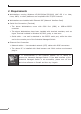
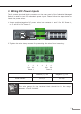
3. Wiring DC Power Inputs
The6-contactterminalblockconnectoron the rearpaneloftheIndustrial Managed
Switchis usedfor twoDC redundantpower input.Please followthe stepsbelow to
insert the power wires.
1.Insert positive/negative DC power wires into contacts 1 and 2 for DC Power 1,
or5and6forDCPower2.
8642
7531
100~240V AC
50/60 Hz
ON
AC POWER
OFF
DC POWER
ON
OFF
AC
RingDC
1
DC
2
Fault
R.O.
DIDO
DC Input Range:
36V~60V
Fault
GNDGNDDO 1DO 0DI 1DI 0
DC 2DC 1
++
2.Tightenthewire-clampscrewsforpreventingthewiresfromloosening.
1 2 3 4 5 6
V1+ V1- V2+ V2-
Power 1 Power 2
Positive(+)Pin Negative(-)Pin
IGSW-24040T Pin1/5 Pin2/6
Note
The wire gauge for the terminal block should be in the range
between12and24AWG.