
User's Manual


18
Step 3: To hang the Industrial Gigabit Ethernet Switch on the
DIN-Rail track or wall, please refer to the Mounting
Installation section.
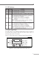
Step 4: Power on the Industrial Gigabit Ethernet Switch. (Please refer
to the Wiring the Power Inputs section for power input.) The
power LED on the Industrial Gigabit Ethernet Switch will
light up. Please refer to the LED Indicators section for the
denition of LED lights.
Step 5: Prepare the twisted-pair, straight through Category 5 cable
for Ethernet connection.
Step 6: Insert one side of Category 5 cables into the Industrial
Gigabit Ethernet Switch Ethernet port (RJ-45 port) and
another side of category 5 cables to the network devices'
Ethernet port (RJ-45 port), eg. Switch, PC or Server. The UTP
port (RJ-45) LED on the Industrial Gigabit Ethernet Switch
will light up when the cable is connected with the network
device. Please refer to the LED Indicators section for the
denition of LED light.
Note
Be sure the connected network devices support MDI/
MDI-X. If it does not support then use the crossover
category 5 Cable.
Step 7: When all connections are all set and all the LED lights show
normally, the installation is completed.