5-/8-Port 10/100/1000Mbps Industrial Gigabit Ethernet Switch IGS-501T/IGS-801T User's Manual
Table of Contents 1. Package Contents....................................................................... 3 2. Hardware Introduction................................................................ 4 2.1 Physical Dimensions............................................................. 4 2.2 Switch Front Panel............................................................... 6 2.3 LED Indicators..................................................................... 7 2.4 Switch Upper Panel.......................
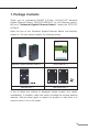
1. Package Contents Thank you for purchasing PLANET 5-/8-Port 10/100/1000T industrial Gigabit Ethernet Switch, IGS-501T/IGS-801T. In the following section, the term “Industrial Gigabit Ethernet Switch” means the IGT-501T/ IGT-801T. Open the box of the Industrial Gigabit Ethernet Switch and carefully unpack it.
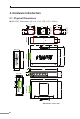
2. Hardware Introduction 2.1 Physical Dimensions IGS-501T dimensions (W x D x H): 135 x 87 x 32mm 40.00 48.80 28.00 18.00 28.00 18.00 28.00 53.50 Rear View 53.50 DIN-Rail Kit Mounting Kit 28.00 18.00 46.50 48.80 39.70 87.80 5 3 2 1 100 LNK ACT P1 LNK ACT 1000 IGS-501T 15.20 Side View 135.00 P2 FAULT 9.20 4 87.80 Top View Side View 32.00 135.00 V1+ V1- PWR1 87.80 PWR2 V2+ V2- Input DC12~48V, AC 24V Bottom View Fault 30.00 87.
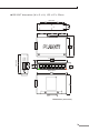
IGS-801T dimensions (W x D x H): 135 x 87 x 32mm Rear View 8 IGS-801T 100 LNK ACT 7 6 5 3 2 1 P2 FAULT LNK ACT 1000 P1 4 Front View Input DC12~48V, AC 24V PWR2 V2+ V2- Fault PWR1 V1+ V1- Side View Top View Bottom View Dimensions ( unit = mm ) 5
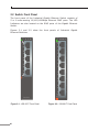
2.2 Switch Front Panel The front panel of the Industrial Gigabit Ethernet Switch consists of 5 or 8 auto-sensing 10/100/1000Mbps Ethernet RJ45 ports. The LED Indicators are also located on the RJ45 ports of the Gigabit Ethernet Switch. Figures 2-1 and 2-2 show the front panels of Industrial Gigabit Ethernet Switches.
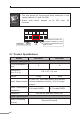
2.3 LED Indicators IGS-501T: LED Color Function P1 Green Lit: indicates power 1 has power. P2 Green Lit: indicates power 2 has power. FAULT Red Lit: indicates either power 1 or power 2 has no power. 1000 Green Lit: indicates the port is successfully connecting to the network at 1000Mbps. Off: indicates that the port is successfully connecting to the network at 10Mbps or 100Mbps. Blinking: indicates that the port is actively sending or receiving data.
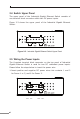
2.4 Switch Upper Panel The upper panel of the Industrial Gigabit Ethernet Switch consists of one terminal block connector within two DC power inputs. Figure 2-3 shows the upper panel of the Industrial Gigabit Ethernet Switch. Figure 2-3: Industrial Gigabit Ethernet Switch Upper Panel 2.5 Wiring the Power Inputs The 6-contact terminal block connector on the top panel of Industrial Gigabit Ethernet Switch is used for two DC redundant power inputs. Please follow the steps below to insert the power wire. 1.
2. Tighten the wire-clamp screws for preventing the wires from loosening. 1 2 Power 1 + Note - 3 4 Fault 5 6 Power 2 + - 1. The wire gauge for the terminal block should be in the range between 12 and 24 AWG. 2. The device must be grounded. 3. The DC power input range is 12V ~ 48V DC. 2.6 Wiring the Fault Alarm Contact The fault alarm contacts are in the middle of the terminal block connector as the picture shows below.
1. The wire gauge for the terminal block should be in the range between 12 and 24 AWG. 2. Alarm relay circuit accepts up to 30V, max. 3A currents. Note Fault Alarm Contacts The Fault Alarm Contacts are energized (CLOSE) for normal operation and will OPEN when failure occurs Fault 2.
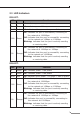
Address Table 2K 4K 1.5Mbits SRAM packet buffer Buffer 1Mbits Flow Control Back pressure for half duplex IEEE 802.3x pause frame for full duplex Switch Fabric 10Gbps 16Gbps Throughput (packet per second) 7.4Mpps 11.9Mpps Jumbo Frame Network Cables 9K 10/100/1000BASE-T: Cat3, 4, 5, 5e, 6 UTP cable (100 meters, max.) EIA/TIA-568 100-ohm STP (100 meters, max.) Standards Conformance Standards Compliance IEEE IEEE IEEE IEEE IEEE IEEE 802.3 Ethernet 802.3u Fast Ethernet 802.
3. Installation 3.1 DIN-rail Mounting Installation The DIN-rail is screwed on the Industrial Gigabit Ethernet Switch when out of factory. When you need to replace the wall-mount application with DIN-rail application on Industrial Gigabit Ethernet Switch, please refer to the following figures to screw the DIN-rail on the Industrial Gigabit Ethernet Switch. To hang the Industrial Gigabit Ethernet Switch, follow the steps below: Step 1: Screw the DIN-rail on the Industrial Gigabit Ethernet Switch.
Step 3: Check whether the DIN-rail is tightly on the track. Step 4: Please refer to the following procedure to remove the Industrial Gigabit Ethernet Switch from the track. Step 5: Lightly pull out the bottom of DIN rail to remove it from the track.
3.2 Wall-mount Plate Mounting To install the Industrial Gigabit Ethernet Switch on the wall, please follow the instructions described below. Step 1: Remove the DIN rail from the Industrial Gigabit Ethernet Switch; loosen the screws to remove the DIN rail. Step 2: Place the wall-mount plate on the rear panel of the Industrial Gigabit Ethernet Switch. Step 3: Use the screws to screw the wall-mount plate on the Industrial Gigabit Ethernet Switch.
4. Troubleshooting This chapter contains information to help you solve issues. If the Industrial Gigabit Ethernet Switch is not functioning properly, make sure the Industrial Gigabit Ethernet Switch was set up according to instructions in this manual. The per port LED is not lit Solution: Check the cable connection of the Industrial Gigabit Ethernet Switch. Performance is bad Solution: Check the speed duplex mode of the partner device.
5. Customer Support Thank you for purchasing PLANET products. You can browse our online FAQ resource and User’s Manual on PLANET Web site first to check if it could solve your issue. If you need more support information, please contact PLANET switch support team. PLANET online FAQ: http://www.planet.com.tw/en/support/faq.php?type=1 Switch support team mail address: support_switch@planet.com.tw Copyright © PLANET Technology Corp. 2017. Contents are subject to revision without prior notice.
APPENDIX A: Networking Connection A.
A.2 RJ45 Cable Pin Assignments The standard RJ45 receptacle/connector There are 8 wires on a standard UTP/STP cable and each wire is colorcoded.
EC Declaration of Conformity For the following equipment: *Type of Product : *Model Number : * Produced by: Manufacturer‘s Name Manufacturer‘s Address 5/8-Port 10/100/1000T Industrial Gigabit Ethernet Switch IGS-501T, IGS-801T : Planet Technology Corp. : 10F., No.96, Minquan Rd., Xindian Dist., New Taipei City 231, Taiwan, R.O.C.