
User's Manual
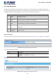
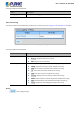


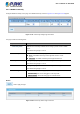
Table Of Contents
- 1. INTRODUCTION
- 2. INSTALLATION
- 3. SWITCH MANAGEMENT
- 4. WEB CONFIGURATION
- 4.1 Main Web Page
- 4.2 System
- 4.3 Port Management
- 4.4 Link Aggregation
- 4.5 VLAN
- 4.5.1 VLAN Overview
- 4.5.2 IEEE 802.1Q VLAN
- 4.5.3 Management VLAN
- 4.5.4 Create VLAN
- 4.5.5 Interface Settings
- 4.5.6 Port to VLAN
- 4.5.7 Port VLAN Membership
- 4.5.8 Protocol VLAN Group Setting
- 4.5.9 Protocol VLAN Port Setting
- 4.5.10 GVRP Setting
- 4.5.11 GVRP Port Setting
- 4.5.12 GVRP VLAN
- 4.5.13 GVRP Statistics
- 4.5.14 VLAN Setting Example:
- 4.6 Spanning Tree Protocol
- 4.7 Multicast
- 4.8 IGMP Snooping
- 4.9 MLD Snooping
- 4.10 LLDP
- 4.11 MAC Address Table
- 4.12 Quality of Service
- 4.13 Security
- 4.14 Ring
- 4.15 Maintenance
- 4.16 Diagnostics
- 5. SWITCH OPERATION
- 6. TROUBLESHOOTING
- APPENDIX A Switch's RJ45 Pin Assignments

User’s Manual of IGS-801M
52
4.2.6 Log Management
The Industrial Managed Switch log management is provided here. The local logs allow you to configure and limit system
messages that are logged to flash or RAM memory. The default is for event levels 0 to 3 to be logged to flash and levels 0 to 6
to be logged to RAM. The following table lists the event levels of the Industrial Managed Switch:
Level Severity Name Description
7 Debug Debugging messages.
6 Informational Informational messages only.
5 Notice Normal but significant condition, such as cold start.
4 Warning Warning conditions (e.g., return false, unexpected return).
3 Error Error conditions (e.g., invalid input, default used).
2 Critical Critical conditions (e.g., memory allocation, or free memory error - resource
exhausted).
1 Alert Immediate action needed.
0 Emergency System unusable.
4.2.6.1 Local Log
The switch system local log information is provided here. The local Log screens in Figure 4-2-12 and Figure 4-2-13 appear.
Figure 4-2-12: Logging Settings Page Screenshot
The page includes the following fields:
Object Description
• Logging Service
Enabled: Enable logging service operation.
Disabled: Disable logging service operation.
Buttons
: Click to apply changes.
Figure 4-2-13: Logging Information Page Screenshot