
User's Manual
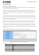
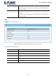
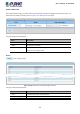

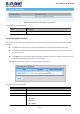
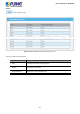
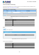
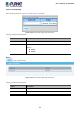
Table Of Contents
- 1. INTRODUCTION
- 2. INSTALLATION
- 3. SWITCH MANAGEMENT
- 4. WEB CONFIGURATION
- 4.1 Main Web Page
- 4.2 System
- 4.3 Port Management
- 4.4 Link Aggregation
- 4.5 VLAN
- 4.5.1 VLAN Overview
- 4.5.2 IEEE 802.1Q VLAN
- 4.5.3 Management VLAN
- 4.5.4 Create VLAN
- 4.5.5 Interface Settings
- 4.5.6 Port to VLAN
- 4.5.7 Port VLAN Membership
- 4.5.8 Protocol VLAN Group Setting
- 4.5.9 Protocol VLAN Port Setting
- 4.5.10 GVRP Setting
- 4.5.11 GVRP Port Setting
- 4.5.12 GVRP VLAN
- 4.5.13 GVRP Statistics
- 4.5.14 VLAN Setting Example:
- 4.6 Spanning Tree Protocol
- 4.7 Multicast
- 4.8 IGMP Snooping
- 4.9 MLD Snooping
- 4.10 LLDP
- 4.11 MAC Address Table
- 4.12 Quality of Service
- 4.13 Security
- 4.14 Ring
- 4.15 Maintenance
- 4.16 Diagnostics
- 5. SWITCH OPERATION
- 6. TROUBLESHOOTING
- APPENDIX A Switch's RJ45 Pin Assignments

User’s Manual of IGS-801M
274
4.13.6.7 Rate Limit
After enabling DHCP snooping, the switch will monitor all the DHCP messages and implement software transmission. The
DHCP Rate Limit Setting and Config screens in Figure 4-13-41 and Figure 4-13-42 appear.
Figure 4-13-41: DHCP Rate Limit Setting Page Screenshot
The page includes the following fields:
Object Description
• Port
Select port from this drop-down list.
• State
Set default or user-define.
• Rate Limit (pps)
Configure the rate limit for the port policer. The default value is "unlimited". Valid
values are in the range 1 to 300.
Buttons
: Click to apply changes
Figure 4-13-42: DHCP Rate Limit Setting Page Screenshot
The page includes the following fields:
Object Description
• Port
The switch port number of the logical port.
• Rate Limit (pps)
Displays the current rate limit.