
User's Manual
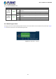
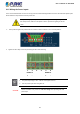
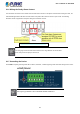
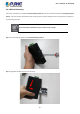
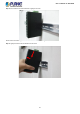
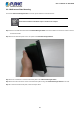
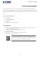
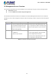
Table Of Contents
- 1. INTRODUCTION
- 2. INSTALLATION
- 3. SWITCH MANAGEMENT
- 4. WEB CONFIGURATION
- 4.1 Main Web Page
- 4.2 System
- 4.3 Port Management
- 4.4 Link Aggregation
- 4.5 VLAN
- 4.5.1 VLAN Overview
- 4.5.2 IEEE 802.1Q VLAN
- 4.5.3 Management VLAN
- 4.5.4 Create VLAN
- 4.5.5 Interface Settings
- 4.5.6 Port to VLAN
- 4.5.7 Port VLAN Membership
- 4.5.8 Protocol VLAN Group Setting
- 4.5.9 Protocol VLAN Port Setting
- 4.5.10 GVRP Setting
- 4.5.11 GVRP Port Setting
- 4.5.12 GVRP VLAN
- 4.5.13 GVRP Statistics
- 4.5.14 VLAN Setting Example:
- 4.6 Spanning Tree Protocol
- 4.7 Multicast
- 4.8 IGMP Snooping
- 4.9 MLD Snooping
- 4.10 LLDP
- 4.11 MAC Address Table
- 4.12 Quality of Service
- 4.13 Security
- 4.14 Ring
- 4.15 Maintenance
- 4.16 Diagnostics
- 5. SWITCH OPERATION
- 6. TROUBLESHOOTING
- APPENDIX A Switch's RJ45 Pin Assignments

User’s Manual of IGS-801M
24
2.1.6 Wiring the Faulty Alarm Contact
The fault alarm contacts are in the middle of the terminal block connector as the picture shows below. Inserting the wires, the
Industrial Managed Switch will detect the fault status of the power failure and then forms an open circuit. The following
illustration shows an application example for wiring the fault alarm contacts.
1
2
3
4
5
6
The wire gauge for the terminal block should be in the range between 12 and 24 AWG.
Alarm relay circuit accepts up to 24V AC,1A.
2.1.7 Grounding the Device
Users MUST complete grounding wired with the device; otherwise, a sudden lightning could cause fatal damage to the device.
EMD (Lightning) DAMAGE IS NOT CONVERED UNDER WARRANTY.
Insert the wires into the fault alarm contacts