
User's Manual
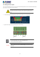
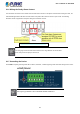
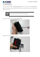
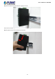
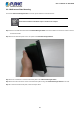
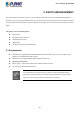
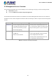
Table Of Contents
- 1. INTRODUCTION
- 2. INSTALLATION
- 3. SWITCH MANAGEMENT
- 4. WEB CONFIGURATION
- 4.1 Main Web Page
- 4.2 System
- 4.3 Port Management
- 4.4 Link Aggregation
- 4.5 VLAN
- 4.5.1 VLAN Overview
- 4.5.2 IEEE 802.1Q VLAN
- 4.5.3 Management VLAN
- 4.5.4 Create VLAN
- 4.5.5 Interface Settings
- 4.5.6 Port to VLAN
- 4.5.7 Port VLAN Membership
- 4.5.8 Protocol VLAN Group Setting
- 4.5.9 Protocol VLAN Port Setting
- 4.5.10 GVRP Setting
- 4.5.11 GVRP Port Setting
- 4.5.12 GVRP VLAN
- 4.5.13 GVRP Statistics
- 4.5.14 VLAN Setting Example:
- 4.6 Spanning Tree Protocol
- 4.7 Multicast
- 4.8 IGMP Snooping
- 4.9 MLD Snooping
- 4.10 LLDP
- 4.11 MAC Address Table
- 4.12 Quality of Service
- 4.13 Security
- 4.14 Ring
- 4.15 Maintenance
- 4.16 Diagnostics
- 5. SWITCH OPERATION
- 6. TROUBLESHOOTING
- APPENDIX A Switch's RJ45 Pin Assignments

User’s Manual of IGS-801M
23
2.1.5 Wiring the Power Inputs
The 6-contact terminal block connector on the top panel of Industrial Managed Switch is used for two redundant power inputs.
Please follow the steps below to insert the power wire.
When performing any of the procedures like inserting the wires or tightening the
wire-clamp screws, make sure the power is OFF to prevent from getting an electric
shock.
1. Insert positive/negative DC power wires into Contacts 1 and 2 for Power 1, or 5 and 6 for power 2.
2. Tighten the wire-clamp screws for preventing the wires from loosening.
1
2
3
4
5
6
Power 1
Power 2
+
-
+
-
1. The power input range is 12V ~ 48V DC and supports 24V AC.
2. Use one power input when using 24V AC.
CAUTION
PWR1 and PWR2 must provide the same DC voltage while operating with dual
power input.