
User's Manual
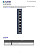
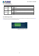
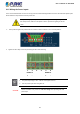
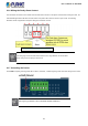
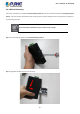
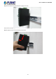
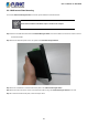
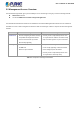
Table Of Contents
- 1. INTRODUCTION
- 2. INSTALLATION
- 3. SWITCH MANAGEMENT
- 4. WEB CONFIGURATION
- 4.1 Main Web Page
- 4.2 System
- 4.3 Port Management
- 4.4 Link Aggregation
- 4.5 VLAN
- 4.5.1 VLAN Overview
- 4.5.2 IEEE 802.1Q VLAN
- 4.5.3 Management VLAN
- 4.5.4 Create VLAN
- 4.5.5 Interface Settings
- 4.5.6 Port to VLAN
- 4.5.7 Port VLAN Membership
- 4.5.8 Protocol VLAN Group Setting
- 4.5.9 Protocol VLAN Port Setting
- 4.5.10 GVRP Setting
- 4.5.11 GVRP Port Setting
- 4.5.12 GVRP VLAN
- 4.5.13 GVRP Statistics
- 4.5.14 VLAN Setting Example:
- 4.6 Spanning Tree Protocol
- 4.7 Multicast
- 4.8 IGMP Snooping
- 4.9 MLD Snooping
- 4.10 LLDP
- 4.11 MAC Address Table
- 4.12 Quality of Service
- 4.13 Security
- 4.14 Ring
- 4.15 Maintenance
- 4.16 Diagnostics
- 5. SWITCH OPERATION
- 6. TROUBLESHOOTING
- APPENDIX A Switch's RJ45 Pin Assignments

User’s Manual of IGS-801M
22
Per 10/100/1000BASE-T Port
LED Color Function
1000
LNK/ACT
Green
Lights
Indicates the port is running at
1000Mbps
speed and successfully
established.
Blinks Indicates that the switch is actively sending or receiving data over that port.
Off
No device is attached
10/100
LNK/ACT
Green
Lights
Indicates the port is running at 10/100Mbps speed and successfully
established.
Blinks Indicates that the switch is actively sending or receiving data over that port.
Off No device is attached
2.1.4 Switch Upper Panel
The upper panel of the Industrial Managed Switch consists of one terminal block connector within two DC power inputs. Figure
2-1-4 shows the upper panel of the Industrial Managed Switch.
Figure 2-1-4: IGS-801M Top View