
User's Manual
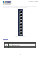
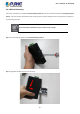
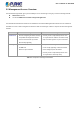
Table Of Contents
- 1. INTRODUCTION
- 2. INSTALLATION
- 3. SWITCH MANAGEMENT
- 4. WEB CONFIGURATION
- 4.1 Main Web Page
- 4.2 System
- 4.3 Port Management
- 4.4 Link Aggregation
- 4.5 VLAN
- 4.5.1 VLAN Overview
- 4.5.2 IEEE 802.1Q VLAN
- 4.5.3 Management VLAN
- 4.5.4 Create VLAN
- 4.5.5 Interface Settings
- 4.5.6 Port to VLAN
- 4.5.7 Port VLAN Membership
- 4.5.8 Protocol VLAN Group Setting
- 4.5.9 Protocol VLAN Port Setting
- 4.5.10 GVRP Setting
- 4.5.11 GVRP Port Setting
- 4.5.12 GVRP VLAN
- 4.5.13 GVRP Statistics
- 4.5.14 VLAN Setting Example:
- 4.6 Spanning Tree Protocol
- 4.7 Multicast
- 4.8 IGMP Snooping
- 4.9 MLD Snooping
- 4.10 LLDP
- 4.11 MAC Address Table
- 4.12 Quality of Service
- 4.13 Security
- 4.14 Ring
- 4.15 Maintenance
- 4.16 Diagnostics
- 5. SWITCH OPERATION
- 6. TROUBLESHOOTING
- APPENDIX A Switch's RJ45 Pin Assignments

User’s Manual of IGS-801M
21
2.1.3 LED Indications
The front panel LEDs indicate instant status of port links, data activity and system power; it helps monitor and troubleshoot
when needed. Figure 2-1-3 shows the LED indications of the Industrial Managed Switch.
Figure 2-1-3: IGS-801M LED Panel
LED Indication
System
LED Color Function
P1 Green Indicates power 1 has power.
P2 Green Indicates power 2 has power.
Fault Green Indicates either power 1 or power 2 has no power.