
User's Manual

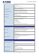
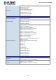

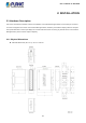
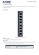
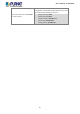
Table Of Contents
- 1. INTRODUCTION
- 2. INSTALLATION
- 3. SWITCH MANAGEMENT
- 4. WEB CONFIGURATION
- 4.1 Main Web Page
- 4.2 System
- 4.3 Port Management
- 4.4 Link Aggregation
- 4.5 VLAN
- 4.5.1 VLAN Overview
- 4.5.2 IEEE 802.1Q VLAN
- 4.5.3 Management VLAN
- 4.5.4 Create VLAN
- 4.5.5 Interface Settings
- 4.5.6 Port to VLAN
- 4.5.7 Port VLAN Membership
- 4.5.8 Protocol VLAN Group Setting
- 4.5.9 Protocol VLAN Port Setting
- 4.5.10 GVRP Setting
- 4.5.11 GVRP Port Setting
- 4.5.12 GVRP VLAN
- 4.5.13 GVRP Statistics
- 4.5.14 VLAN Setting Example:
- 4.6 Spanning Tree Protocol
- 4.7 Multicast
- 4.8 IGMP Snooping
- 4.9 MLD Snooping
- 4.10 LLDP
- 4.11 MAC Address Table
- 4.12 Quality of Service
- 4.13 Security
- 4.14 Ring
- 4.15 Maintenance
- 4.16 Diagnostics
- 5. SWITCH OPERATION
- 6. TROUBLESHOOTING
- APPENDIX A Switch's RJ45 Pin Assignments

User’s Manual of IGS-801M
19
2.1.2 Switch Front Panel
The front panel provides a simple interface monitoring of the Industrial Managed Switch. Figure 2-1-2 shows the front panel of
the Industrial Managed Switch.
Front View
Figure 2-1-2: IGS-801M Front Panel
■ Gigabit TP Interface
10/100/1000BASE-T copper, RJ45 twisted-pair: Up to 100 meters.
■ Reset Button
On the left of the front panel, the reset button is designed to reboot the Industrial Managed Switch without turning off and
on the power. The following is the summary table of reset button functions:
Reset Button
Function
Press the reset button for < 5 seconds
for system reboot.
Reboot the Industrial Managed Switch.