
User's Manual
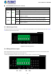

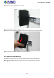

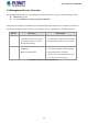
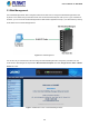
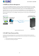
Table Of Contents
- 1. INTRODUCTION
- 2. INSTALLATION
- 3. SWITCH MANAGEMENT
- 4. WEB CONFIGURATION
- 4.1 Main Web Page
- 4.2 System
- 4.3 Port Management
- 4.4 Link Aggregation
- 4.5 VLAN
- 4.5.1 VLAN Overview
- 4.5.2 IEEE 802.1Q VLAN
- 4.5.3 Management VLAN
- 4.5.4 Create VLAN
- 4.5.5 Interface Settings
- 4.5.6 Port to VLAN
- 4.5.7 Port VLAN Membership
- 4.5.8 Protocol VLAN Group Setting
- 4.5.9 Protocol VLAN Port Setting
- 4.5.10 GVRP Setting
- 4.5.11 GVRP Port Setting
- 4.5.12 GVRP VLAN
- 4.5.13 GVRP Statistics
- 4.5.14 VLAN setting example:
- 4.6 Spanning Tree Protocol
- 4.7 Multicast
- 4.8 Quality of Service
- 4.9 Security
- 4.10 ACL
- 4.11 MAC Address Table
- 4.12 LLDP
- 4.13 Diagnostics
- 4.14 RMON
- 4.15 Maintenance
- 5. SWITCH OPERATION
- 6. TROUBLESHOOTING
- APPENDIX A Switch's RJ45 Pin Assignments
- EC Declaration of Conformity

User’s Manual of IGS-801M
2.2 Mounting Installation
This section describes how to install your Industrial Managed Switch and make connections to the Industrial Managed Switch.
Please read the following topics and perform the procedures in the order being presented. To install your Industrial Managed
Switch on a desktop or shelf, simply complete the following steps.
2.2.1 DIN-rail Mounting
The DIN-rail is screwed on the Industrial Managed Switch when out of factory. When you need to replace the wall mount
application with DIN-rail application on Industrial Managed Switch, please refer to the following figures to screw the DIN-rail on
the Industrial Managed Switch. To hang the Industrial Managed Switch, follow the steps below:
Step 1: Screw the DIN-rail on the Industrial Managed Switch.
24