
User's Manual
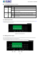
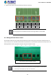
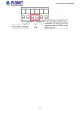
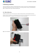
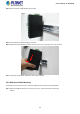
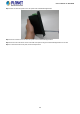
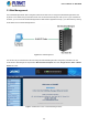
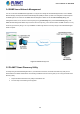
Table Of Contents
- 1. INTRODUCTION
- 2. INSTALLATION
- 3. SWITCH MANAGEMENT
- 4. WEB CONFIGURATION
- 4.1 Main Web Page
- 4.2 System
- 4.3 Port Management
- 4.4 Link Aggregation
- 4.5 VLAN
- 4.5.1 VLAN Overview
- 4.5.2 IEEE 802.1Q VLAN
- 4.5.3 Management VLAN
- 4.5.4 Create VLAN
- 4.5.5 Interface Settings
- 4.5.6 Port to VLAN
- 4.5.7 Port VLAN Membership
- 4.5.8 Protocol VLAN Group Setting
- 4.5.9 Protocol VLAN Port Setting
- 4.5.10 GVRP Setting
- 4.5.11 GVRP Port Setting
- 4.5.12 GVRP VLAN
- 4.5.13 GVRP Statistics
- 4.5.14 VLAN setting example:
- 4.6 Spanning Tree Protocol
- 4.7 Multicast
- 4.8 Quality of Service
- 4.9 Security
- 4.10 ACL
- 4.11 MAC Address Table
- 4.12 LLDP
- 4.13 Diagnostics
- 4.14 RMON
- 4.15 Maintenance
- 5. SWITCH OPERATION
- 6. TROUBLESHOOTING
- APPENDIX A Switch's RJ45 Pin Assignments
- EC Declaration of Conformity

User’s Manual of IGS-801M
■ 10/100/1000BASE-T Interfaces (Port-1 to Port-8)
LED Color Function
Lights
Indicates the port is successfully connecting to the network at 1000Mbps
Blinks
Indicates that the port is actively sending or receiving data over that port
1000 Green
Off
Indicates that no device is attached or it is successfully connecting to the network
at 10Mbps or 100Mbps
Lights
Indicates the port is successfully connecting to the network at 100Mbps
Blinks
Indicates that the port is actively sending or receiving data over that port
10/100 Green
Off
No device is attached
2.1.3 Switch Upper Panel
The upper panel of the Industrial Managed Switch consists of one terminal block connector within two DC power inputs. Figure
2-3 shows the upper panel of the switch.
Figure 2-3: IGS-801M Upper Panel
2.1.4 Wiring the Power Inputs
The 6-contact terminal block connector on the top panel of Industrial Managed Switch is used for two DC redundant power
inputs. Please follow the steps below to insert the power wire.
1. Insert positive/negative DC power wires into contacts 1 and 2 for Power 1 or 5 and 6 for Power 2.
V1- V1 + V2 - V2 +
21