
User's Manual

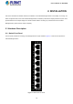
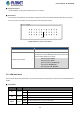
Table Of Contents
- 1. INTRODUCTION
- 2. INSTALLATION
- 3. SWITCH MANAGEMENT
- 4. WEB CONFIGURATION
- 4.1 Main Web Page
- 4.2 System
- 4.3 Port Management
- 4.4 Link Aggregation
- 4.5 VLAN
- 4.5.1 VLAN Overview
- 4.5.2 IEEE 802.1Q VLAN
- 4.5.3 Management VLAN
- 4.5.4 Create VLAN
- 4.5.5 Interface Settings
- 4.5.6 Port to VLAN
- 4.5.7 Port VLAN Membership
- 4.5.8 Protocol VLAN Group Setting
- 4.5.9 Protocol VLAN Port Setting
- 4.5.10 GVRP Setting
- 4.5.11 GVRP Port Setting
- 4.5.12 GVRP VLAN
- 4.5.13 GVRP Statistics
- 4.5.14 VLAN setting example:
- 4.6 Spanning Tree Protocol
- 4.7 Multicast
- 4.8 Quality of Service
- 4.9 Security
- 4.10 ACL
- 4.11 MAC Address Table
- 4.12 LLDP
- 4.13 Diagnostics
- 4.14 RMON
- 4.15 Maintenance
- 5. SWITCH OPERATION
- 6. TROUBLESHOOTING
- APPENDIX A Switch's RJ45 Pin Assignments
- EC Declaration of Conformity

User’s Manual of IGS-801M
2. INSTALLATION
This section describes the hardware features and installation of the Industrial Managed Switch on the desktop or mounting. For
easier management and control of the Industrial Managed Switch, familiarize yourself with its display indicators and ports. Front
panel illustrations in this chapter display the unit LED indicators. Before connecting any network device to the Industrial
Managed Switch, please read this chapter completely.
2.1 Hardware Description
2.1.1 Switch Front Panel
The front panel provides the monitoring of the Managed Switch’s simple interfaces. Figure 2-1 shows the front panel of the
Industrial Managed Switch.
Figure 2-1 IGS-801M Front Panel
19