
Quick Guide

5
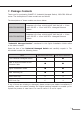
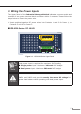
3. Wiring the Power Inputs
TheUpperPanelofthe Industrial Managed Switch indicates a power socket and
consists of one green terminal block connector within 6 contacts. Please follow the
steps below to insert the power wire.
1.Insert positive/negative DC power wires into Contacts 1 and 2 for Power 1, or
Contacts 5 and 6 for Power 2.
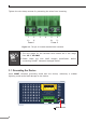
IGS-6329-Series: DC 48-54V
DO0DO1 DI0GNDGND
PWR1
PWR2
Alarm
DC Input:
48-54V , 8A max.
Max. Fault Alarm Loading: 24V, 1A
Dual power input is required
for maximum PoE loading.
Refer to user’s manual for
more details.
DI1
1 2 3 4 5 6
1 2 3 4 5 6
Figure 3-1: IGS-6329-Series Upper Panel
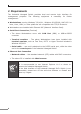
Note
DualpowerinputisrequiredformaximumPoEloading
Single power input: Maximum 240-wattPoEbudget
Dual power input: Maximum 360-wattPoEbudget
Caution
PWR1 and PWR2 must provide exactly the same DC voltage for
power load balance while operating with dual power input.