Industrial L3 Multi-Port Gigabit Managed Ethernet Switch IGS-6329 DIN-rail Series Quick Installation Guide
Table of Contents 1. Package Contents........................................................................................ 3 2. Requirements.............................................................................................. 4 3. Wiring the Power Inputs............................................................................... 5 3.1 Grounding the Device........................................................................... 6 4. Terminal Setup............................................
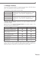
1. Package Contents Thank you for purchasing PLANET L3 Industrial Managed Switch, IGS-6329 DIN-rail series. The descriptions of these models are as follows: The descriptions of these models are shown below: IGS-6329-8UP2S2X Industrial L3 8-Port 10/100/1000T 802.3bt PoE + 2-Port 1G/2.5G SFP + 2-Port 10G SFP+ Managed Ethernet Switch IGS-6329-8UP2S4X Industrial L3 8-Port 10/100/1000T 802.3bt PoE + 2-Port 1G/2.
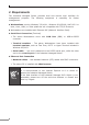
2. Requirements The Industrial Managed Switch provides local and remote login interface for management purposes. The following equipment is necessary for further management: zz Workstations running Windows 7/8/10/11, Windows 2012/2008, MAC OS X or later, Linux, UNIX, or other platforms are compatible with TCP/IP Protocols. zz Workstations are installed with Ethernet NIC (Network Interface Card). zz Serial Port Connection (Terminal) The above Workstations come with COM Port (DB9) or USB-to-RS232 converter.
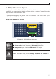
3. Wiring the Power Inputs The Upper Panel of the Industrial Managed Switch indicates a power socket and consists of one green terminal block connector within 6 contacts. Please follow the steps below to insert the power wire. 1. Insert positive/negative DC power wires into Contacts 1 and 2 for Power 1, or Contacts 5 and 6 for Power 2. IGS-6329-Series: DC 48-54V GND GND DO1 DO0 DI1 DI0 1 2 3 4 5 6 Dual power input is required for maximum PoE loading. Refer to user’s manual for more details. Max.
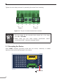
Tighten the wire-clamp screws for preventing the wires from loosening. 1 2 V+ VPower 1 3 4 5 6 V+ VPower 2 Figure 3-2: The pin of 6-contact terminal block connector 1. The wire gauge for the terminal block should be in the range from 12 to 24 AWG. Note 2. Please check the wire AWG Ampere specification connecting PLANET Industrial Managed Switch. before 3.1 Grounding the Device Users MUST complete grounding wired with the device; otherwise, a sudden lightning could cause fatal damage to the device.
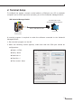
4. Terminal Setup To configure the system, connect a serial cable to a COM port on a PC or notebook computer and to RJ45 type serial (console) port of the Industrial Managed Switch. IGS Industrial Managed Switch PC/Workstation with Terminal Emulation Software Console 115200,N,8,1 RJ45 to DB9 RS232 Cable Console Port 115200,N,8,1 Serial Port A terminal program is required to make the software connected to the Industrial Managed Switch. 1. Run terminal program on the OS. 2.
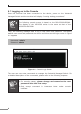
4.1 Logging on to the Console Once the terminal has been connected to the device, power on the Industrial Managed Switch and the terminal will display “running testing procedures”. Note The following console screen is based on the IGS-6329-8UP2S4X. The display of the IGS-6329 series is the same as that of the IGS-6329-8UP2S4X. Then, the following message asks to log in user name and password.
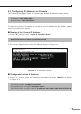
4.2 Configuring IP Address via Console The Industrial Managed Switch is shipped with default IP address shown below: IP Address: 192.168.0.100 Subnet Mask: 255.255.255.0 To check the current IP address or modify a new IP address for the Switch, please use the procedure as follows: Display of the Current IP Address 1. At the “#” prompt, enter “show ip interface brief”. IGS-6329-Series # show ip interface brief 2. The screen displays the current IP address shown in Figure 4-2.
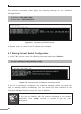
The previous command would apply the following settings for the Industrial Managed Switch. IP Address: 192.168.1.100 Subnet Mask: 255.255.255.0 Figure 4-3: Configuring IP Address Screen 4. Repeat step 1 to check if the IP address has changed. 4.3 Storing Current Switch Configuration 1. At the “#” prompt, enter the following command and press .
5. Starting Web Management The following shows how to start up the Web Management of the Industrial Managed Switch. Note the Industrial Managed Switch is configured through an Ethernet connection. Please make sure the manager PC must be set to the same IP subnet address. For example, the default IP address of the Industrial Managed Switch is 192.168.0.100, then the manager PC should be set to 192.168.0.x (where x is a number between 1 and 254, except 100), and the default subnet mask is 255.255.255.0.
2. When the following dialog box appears, please enter the default user name “admin” and password “admin” (or the password you have changed before) as shown in Figure 5-2. Default IP Address: 192.168.0.100 Default Username: admin Default Password: admin Figure 5-2: Login Screen 3. After entering the password, the main screen appears as shown in Figure 5-3.
The Switch Menu on the top of the Web page lets you access all the commands and statistics the Industrial Managed Switch provides. The Switch Menu always contains one or more buttons, such as “System”, “Switching”, “Routing”, “QoS”, “Security”, “PoE”, “Ring”, “ONVIF” and “Maintenance”. Figure 5-4: Switch Menu Figure 5-5: Example of Switch Sub-menu Now, you can use the Web management interface to continue the Switch management. Please refer to the user manual for more.
5.2 Saving Configuration via Web To save all applied changes and set the current configuration as a startup configuration, the startup-configuration file will be loaded automatically across a system reboot. 1. Click the Save icon on the top Switch Menu bar. 2. Press the “Save Configuration” button. 3. Or the other way to save the setting is to Click Maintenance, Save Startup Config.
6. Recovering Back to Default Configuration IP address has been changed or admin password has been forgotten – To reset the IP address to the default IP address “192.168.0.100” and the user password to factory default mode (default password is admin), press the hardware-based reset button on the front panel for about 5~10 seconds. After the device is rebooted, you can log in the management Web interface within the same subnet of 192.168.0.xx and default password.
7. Customer Support Thank you for purchasing PLANET products. You can browse our online FAQ resource on PLANET web site first to check if it could solve your issue. If you need more support information, please contact PLANET switch support team. PLANET online FAQs: http://www.planet.com.tw/en/support/faq Switch support team mail address: support@planet.com.tw IGS-6329-DIN-rail Series User’s Manual: https://www.planet.com.